Thermal neutron porosity from neutron slowing-down length, formation thermal neutron capture cross section, and bulk density

a technology neutron slowing down, which is applied in the direction of measurement devices, nuclear radiation detection, instruments, etc., can solve the problems of less desirable chemical sources, less common use of thermal neutron porosity measurements obtained with chemical source tools, and interference of borehole fluids with neutron measurements

Active Publication Date: 2010-02-23
SCHLUMBERGER TECH CORP
View PDF7 Cites 17 Cited by
  • Summary
  • Abstract
  • Description
  • Claims
  • Application Information

AI Technical Summary

Problems solved by technology

Since neutrons interact with hydrogenous materials, borehole fluids will interfere with neutron measurements.
Even though the hydrogen index measurements, which are less susceptible to interference from neutron absorbers, can provide more accurate pore space estimates, they are not as commonly used as the thermal neutron porosity measurements obtained with chemical source tools.
However, chemical sources are less desirable due to their constant emission of radiation and strict government regulations.
In addition, these chemical sources are becoming scarce.

Method used


Image

  • Thermal neutron porosity from neutron slowing-down length, formation thermal neutron capture cross section, and bulk density
  • Thermal neutron porosity from neutron slowing-down length, formation thermal neutron capture cross section, and bulk density
  • Thermal neutron porosity from neutron slowing-down length, formation thermal neutron capture cross section, and bulk density

Examples


Embodiment Construction

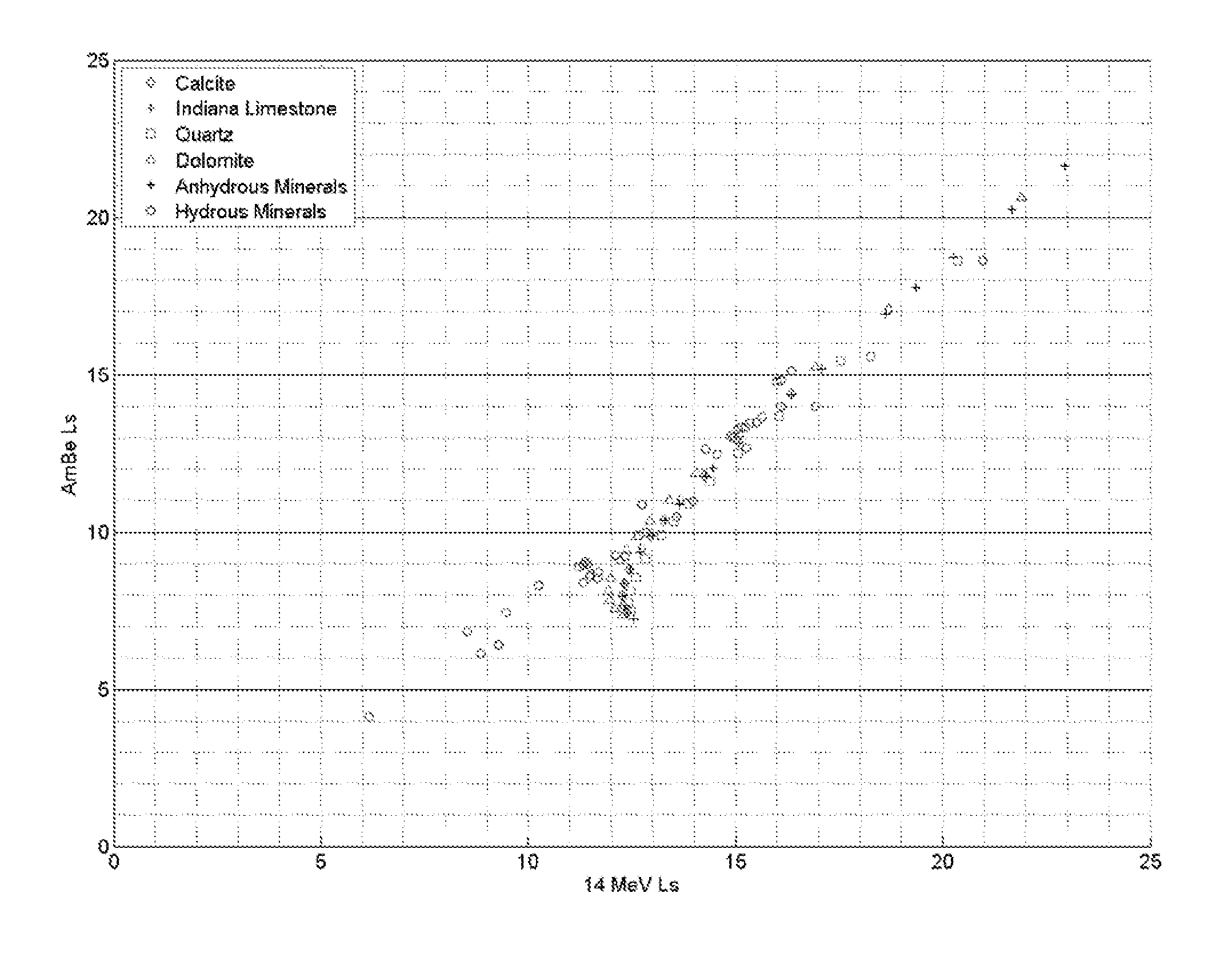
[0024]Embodiments of the invention relate to methods for converting measurements made with a first tool into corresponding desired measurements that would have been made if a second tool were used. The first tool and the second tool may have different neutron sources and / or different neutron detectors. Different neutron sources, for example, may include AmBe, californium (Cf), dueterium-deuterium (DD) neutron generator, and deuterium-tritium (DT) neutron generator. Different neutron detectors, for example, may include thermal neutron detectors, epithermal neutron detectors, and fast neutron detectors.

[0025]For example, methods of the invention may be used to derive traditional thermal neutron porosities from epithermal neutron measurements made with electronic source neutron tools. As noted above, some modern neutron tools use electronic neutron sources that emit neutrons at higher energies. Some of these tools are designed to measure epithermal neutrons that return from the formati...


PUM


Abstract

A method for determining at least one formation property calculated from neutron measurements acquired with a downhole tool includes emitting neutrons from a source in the tool into the formation, detecting neutrons with at least one detector in the downhole tool, calculating a first slowing-down length (L1) based on the detected neutrons, and deriving a second slowing-down length (L2) based on the first slowing-down length (L1). Further steps include deriving a correlation function for relating slowing-down lengths from a first tool to slowing-down lengths associated with a different source, wherein the correlation function depends on formation properties such as bulk density; and applying the correlation function to the slowing-down length of the first tool to derive the slowing-down length of the second tool. A method for determining a thermal neutron formation porosity based on a slowing-down length from epithermal neutron measurements from an electronic neutron source includes converting the slowing-down length into a computed neutron slowing-down length from thermal neutron measurements from a chemical neutron source, wherein the converting uses a correlation function that depends on formation bulk density; deriving a thermal neutron countrate ratio based on the computed neutron slowing-down length, wherein the deriving uses a function that depends on the formation bulk density and formation sigma; and computing the thermal neutron formation porosity from the thermal neutron countrate ratio.

Description

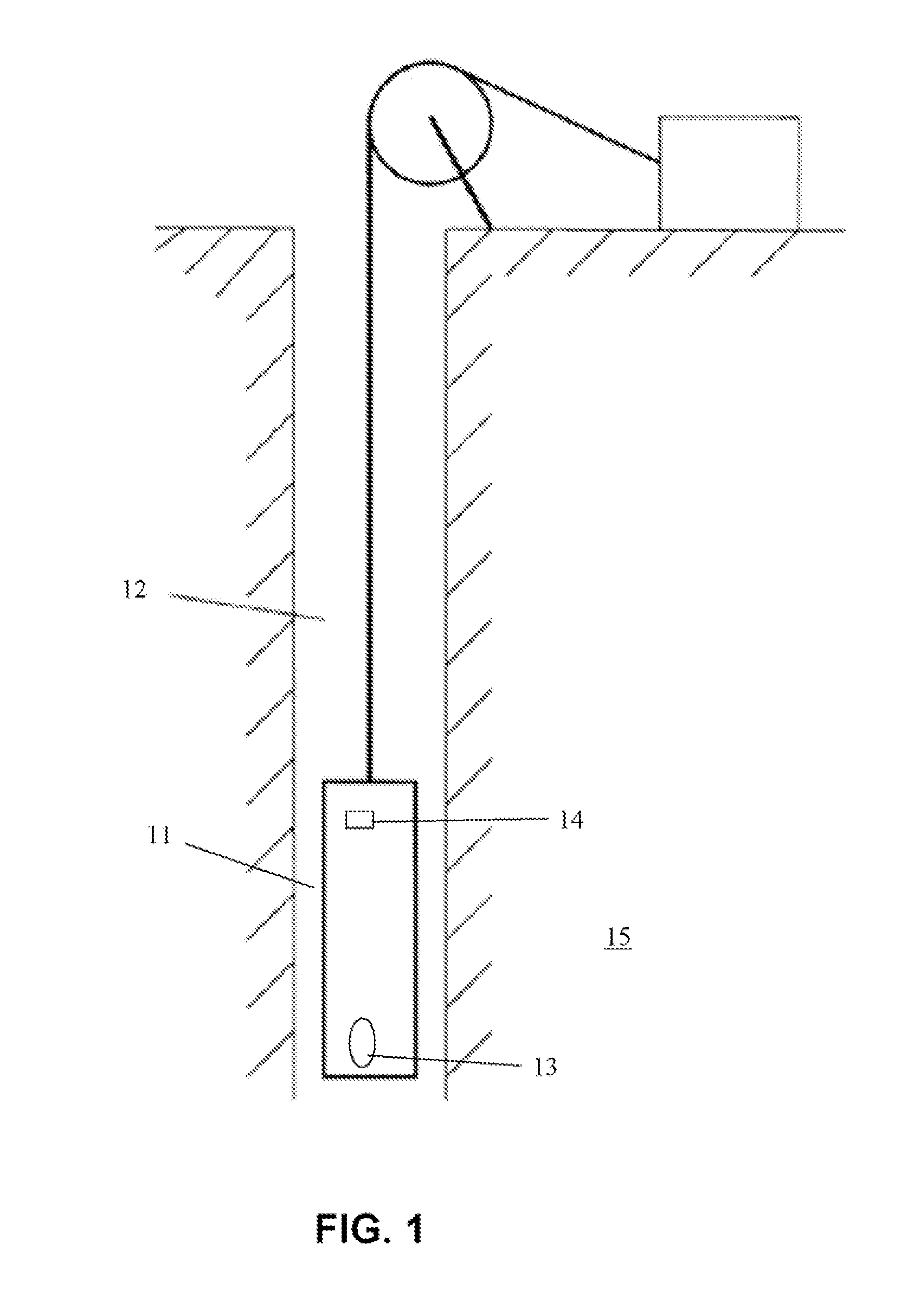
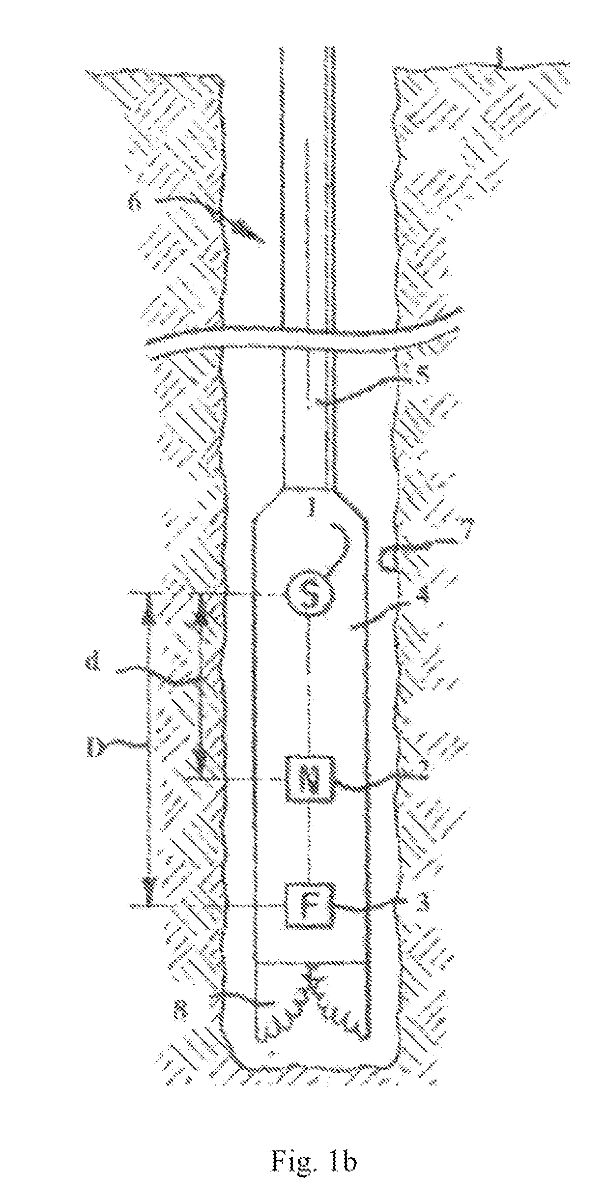
BACKGROUND OF INVENTION[0001]1. Field of invention[0002]This invention relates to the determination of formation porosity using neutron measurements.[0003]2. Background Art[0004]In hydrocarbon exploration and production, it is important to determine whether an earth formation contains hydrocarbon and how much hydrocarbon is in the formation. Neutron “porosity” tools are traditionally used to determine the amount of hydrocarbon and water present in pore spaces of earth formations.[0005]A neutron tool contains a neutron-emitting source (either a chemical source or a neutron generator) and one or more axially spaced detectors that respond to the flux of impinging neutrons resulting from the interactions of neutrons with nuclei within the borehole and formation in the vicinity of the borehole. The basic concept of a neutron porosity tool is predicated on the fact that (a) hydrogen is the most effective moderator of neutrons and that (b) most hydrogen found in earth formations is contain...

Claims


Application Information

Patent Timeline
Patent Type & Authority Patents(United States)
IPC IPC(8): G01V5/10
CPCG01V5/107
Inventor FRICKE, SCOTT H.ADOLPH, ROBERT A.EVANS, MIKE
Owner SCHLUMBERGER TECH CORP
Why Eureka
Try Eureka