Primary neutron source part for starting nuclear reactor

A nuclear reactor and neutron source technology, applied in the field of radioisotope preparation, can solve the problems of difficult cleaning and transportation of neutron source parts, achieve long-term effective operation, improve radiation safety performance, and save space for parts

Inactive Publication Date: 2011-11-16
CHINA INSTITUTE OF ATOMIC ENERGY
View PDF3 Cites 6 Cited by
  • Summary
  • Abstract
  • Description
  • Claims
  • Application Information

AI Technical Summary

Problems solved by technology

[0005] For example, in the journal "Isotope" published in November 1995, "Qinshan 300MW Nuclear Power Plant 210 Design and Safety Analysis of Po-Be Starting Source" and "Manufacture of Mei-Beryllium Annular Neutron Source" in the journal "Nuclear Science and Engineering" published in December 1997 respectively discuss the requirements of nuclear power plant pressurized water reactors. 210 The Po-Be start-up source is described, and the safety of the source is explained. The neutron source part is a commonly used structure at present. The neutron source part of this structure is not easy to clean and transport

Method used


Image

  • Primary neutron source part for starting nuclear reactor
  • Primary neutron source part for starting nuclear reactor

Examples


Embodiment 1

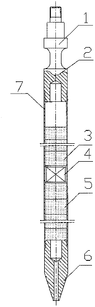
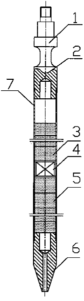
[0022] One-time assembly of neutron source components: first determine the number of neutron sources 5 assembled in the active area of ​​the component, and according to the neutron yield of Cf-252 self-fission, this embodiment adopts a mass of 43.3×10 -6 The neutron source 4 of g, wherein the neutron emission rate of the neutron source 4 is 1.0×10 8 n / s, the compression pad 3 is made of alumina gasket, the support pad 5 is made of alumina gasket, and then the upper end plug 2, the compression pad 3, and the neutron source are sequentially assembled 4. Support the cushion block 5, and fix the neutron source 4 in the active area in the cladding tube 7, and assemble the lower end plug 6 after assembly.

[0023] The upper and lower end plugs 2, 6 of the primary neutron source part are welded and sealed on the cladding tube 7: first, the upper and lower end plugs 2, 6 of the sealed part are welded by argon arc welding. Then, from the helium inlet of the lower end plug 6, 1.5 MPa h...

Embodiment 2

[0026] This embodiment is the same as Embodiment 1, the difference is that this embodiment adopts a mass of 43.3×10 -6 The neutron source 4 of g, wherein the neutron emission rate of the neutron source 4 is 1.0×10 8 n / s, then, sequentially assemble the upper end plug 2, the compression spacer 3, the neutron source 4, the support spacer 5, and fix the neutron source 4 in the active area at the center position of the cladding tube 7, after assembly , Assemble the lower end plug 6. Fill the cladding tube 7 with 1.5MPa helium gas from the helium gas inlet of the lower end plug 6 .

Embodiment 3

[0028] This embodiment is the same as Embodiment 1, the difference is that this embodiment adopts a mass of 129.9×10 -6 The neutron source 4 of g, wherein the neutron emission rate of the neutron source 4 is 3.0×10 8 n / s, the compression cushion block 3 is a compression cushion block made of stainless steel, and the support cushion block 5 is a support cushion block made of stainless steel. Assemble the upper end plug 2, the compression block 3, the neutron source 4, the support block 5 in sequence, and assemble the lower end plug 6. From the helium inlet of the lower end plug 6, fill the cladding tube 7 with 1.2MPa helium.


PUM


Abstract

The invention discloses a primary neutron source part for starting a nuclear reactor. The primary neutron source part comprises a cladding tube, a neutron source, cushion blocks, an upper end plug and a lower end plug, wherein the neutron source is arranged in the cladding tube; two ends of the cladding tube are respectively sealed by the upper end plug and the lower end plug; the neutron source is a Cf-252 neutron source of which neutron emission rate is 1.0*10<8> to 1.0*10<10> n / s; and a compression cushion block and a supporting cushion block are arranged on two sides of the neutron source. The primary neutron source part for starting the nuclear reactor provided by the invention is simple in structure, safe, reliable and easy to process.

Description

technical field [0001] The invention relates to the technical field of radioisotope preparation, in particular to a primary neutron source component for starting a nuclear reactor. Background technique [0002] The reactor start-up of a nuclear power plant must use an isotopic neutron source for primary start-up. Before the initial operation of the reactor, or after a long-term shutdown, there are very few neutrons in the core. If it is started at this time, the nuclear instrument outside the core cannot detect the neutron fluence rate level in the reactor. In order to start the reactor safely, it is necessary to strictly control The growth rate of the effective value-added factor must keep track of the subcriticality of the reactor to prevent the reactor from reaching an uncontrolled instantaneous critical state. For this reason, neutron source components are installed in the core, and these neutron sources can provide enough neutrons, so that the source range nuclear inst...

Claims


Application Information

Patent Timeline
Patent Type & Authority Applications(China)
IPC IPC(8): G21G4/02
CPCG21C5/02G21C7/34G21G4/02Y02E30/30
Inventor 崔海平汪幼梅杨瑞金陈洪涛何舜尧王晓静段利民张春保薛全义龚凌凌杨新李梓
Owner CHINA INSTITUTE OF ATOMIC ENERGY
Why Eureka
Try Eureka