
Thermal head and method of controlling thermal head

a technology of thermal head and thermal head, which is applied in the direction of measuring devices, instruments, printing, etc., can solve the problems of difficult to individually form dots with difficult to independently drive difficult to control the temperature of the respective heat elements, so as to prevent excessive temperature rise of the thermal head and occurrence of “tailing”, suppress the deterioration of the thermal head, and prolong the life of the thermal head

Inactive Publication Date: 2010-02-23
SONY CORP
View PDF4 Cites 0 Cited by
  • Summary
  • Abstract
  • Description
  • Claims
  • Application Information

AI Technical Summary

Benefits of technology

The patent text describes a thermal head with multiple heat elements arranged in a main scanning direction to form a heat generating element row. The heat elements can be controlled independently, but there are limitations in driving them simultaneously. The technique also has limitations in driving the heat elements to form dots in the same position. The patent proposes a new technique that allows for more efficient driving and better control of heat generation to achieve high-quality recording and high-speed recording.

Problems solved by technology

In other words, in the technique disclosed in Patent Document 1, it is difficult to independently drive the respective heat elements.
Since one of the heat elements is affected by heat accumulation of the other, it is difficult to control the temperatures of the respective heat elements.
Moreover, it is difficult to individually form dots with the respective heat elements.
However, Patent Document 2 does not disclose such a point.

Method used


Image

  • Thermal head and method of controlling thermal head
  • Thermal head and method of controlling thermal head
  • Thermal head and method of controlling thermal head

Examples


Embodiment Construction

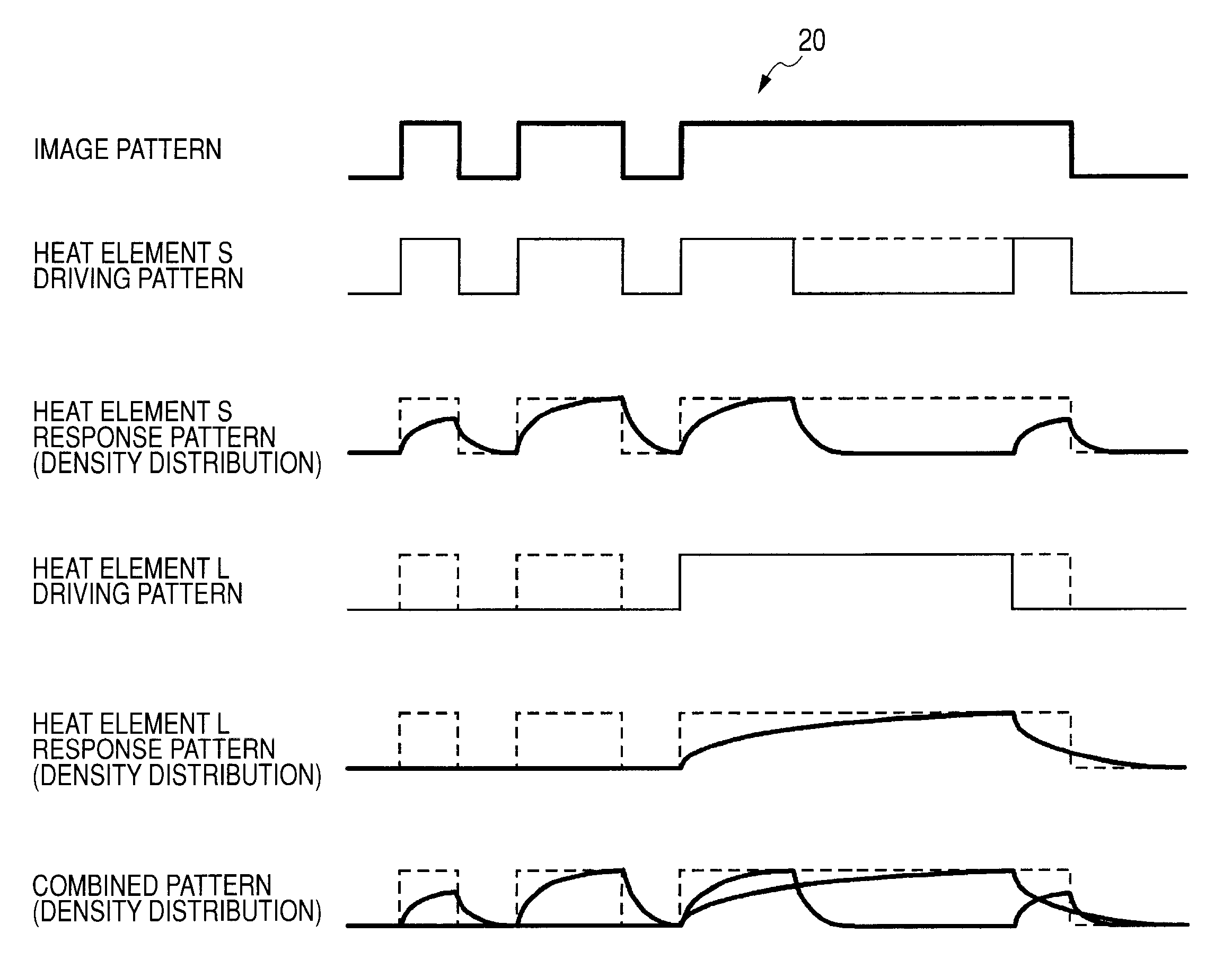
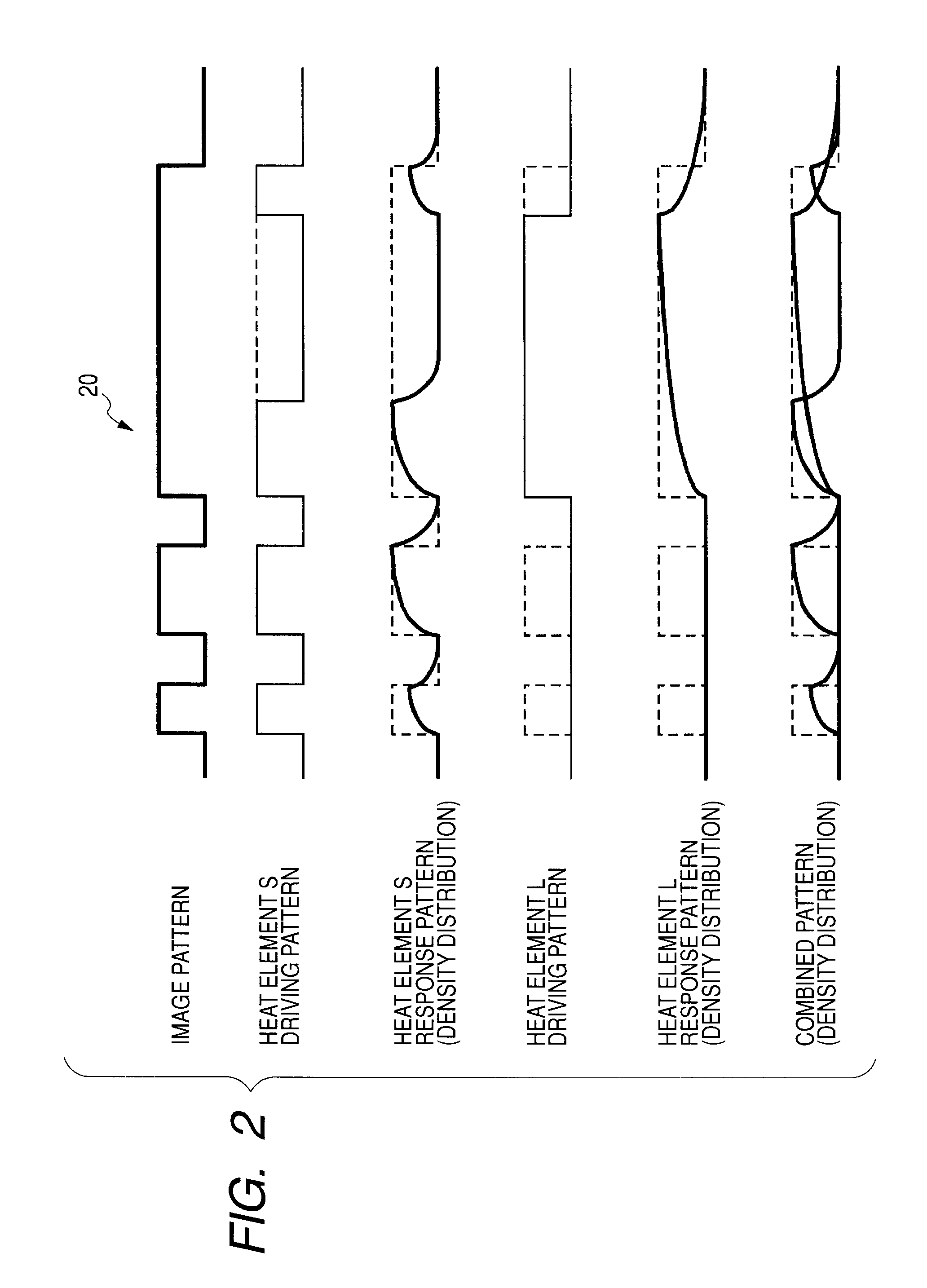
[0049]Embodiments of the present invention will be hereinafter explained in detail with reference to the accompanying drawings. In the embodiments, a heat element is equivalent to a heat generating element and a heat element row is equivalent to a heat generating element row in the present invention.

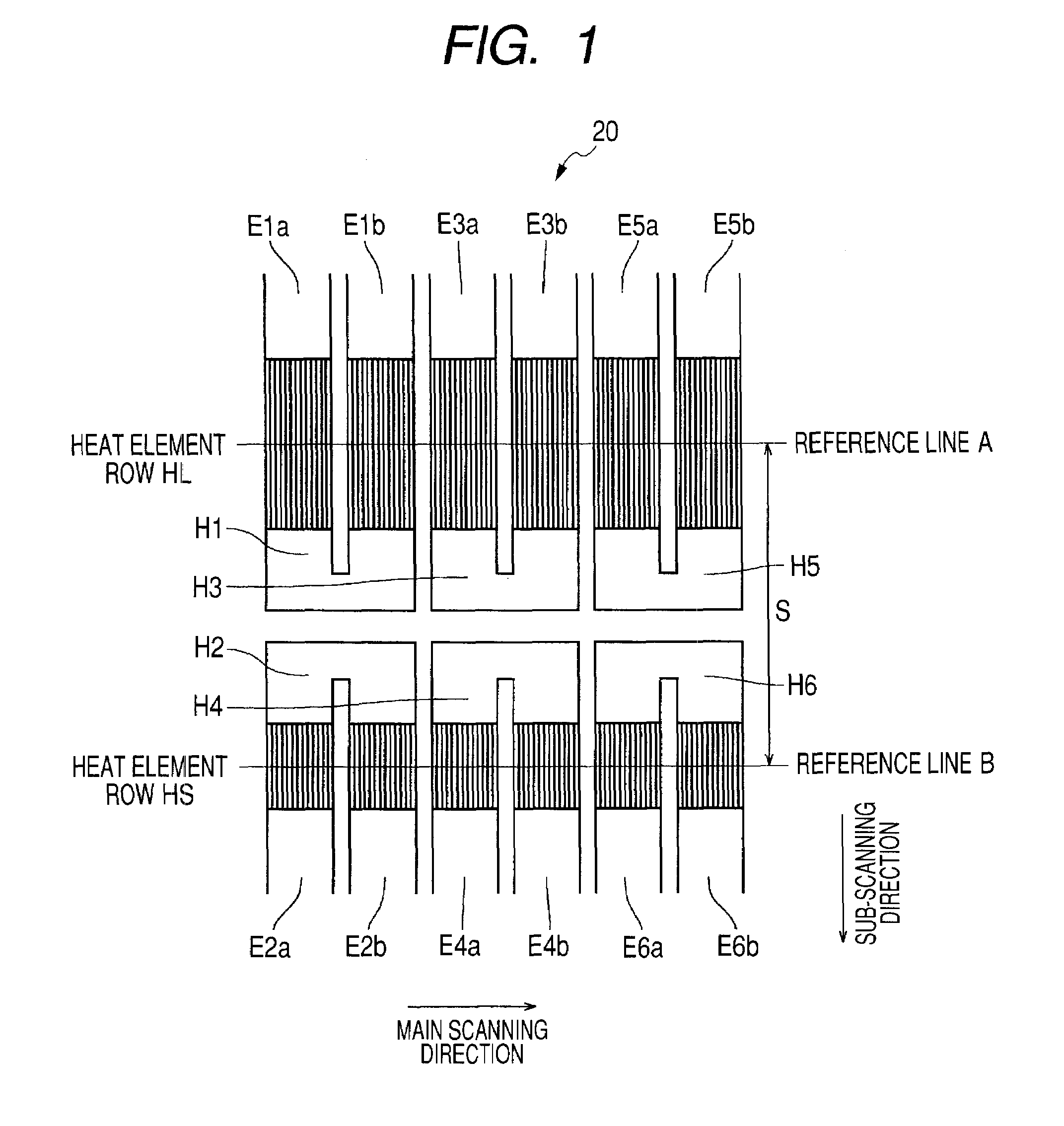
[0050]FIG. 1 is a plan view showing a thermal head 20 according to an embodiment of the present invention.

[0051]As shown in FIG. 1, heat elements H (H1, H2, H3, H4, H5, H6, etc.) are arrayed in the thermal head 20 according to this embodiment. The heat elements H1, H3, H5, and the like are arrayed in a main scanning direction to form a heat element row HL. The heat elements H2, H4, H6, and the like are arrayed in the main scanning direction to form a heat element row HS. The resolution of the thermal head 20 is 300 DPI. 2560 heat elements H1, H3, H5, and the like and 2560 heat elements H2, H4, H6, and the like are arrayed in the heat element row HL and the heat element row HS, respective...


PUM


Abstract

A thermal head has plural heat generating elements arrayed therein in a main scanning direction to form a heat generating element row, causes the respective heat generating elements to generate heat while conveying a recording medium in a sub-scanning direction, and forms plural dot lines in the main scanning direction on the recording medium to record an image. A plurality of the heat generating element rows are arrayed in the sub-scanning direction. Respective nth (n is a natural number) heat generating elements among the heat generating elements in the respective heat generating element rows can sharingly form a dot in the same position in an identical dot line according to independent driving for each of the heat generating element rows.

Description

CROSS-REFERENCES TO RELATED APPLICATIONS[0001]The present invention contains subject matter related to Japanese Patent Application JP 2006-313646 filed in the Japanese Patent Office on Nov. 20, 2006, the entire contents of which being incorporated herein by reference.BACKGROUND OF THE INVENTION[0002]1. Field of the Invention[0003]The present invention relates to a thermal head that has plural heat generating elements arrayed therein in a main scanning direction and causes, while conveying a recording medium in a sub-scanning direction, the respective heat generating elements to generate heat to record an image and the like on a recording medium and a method of controlling the thermal head, and, more particularly to a technique adapted to obtain a high recording quality with high density.[0004]2. Description of the Related Art[0005]There is known a thermal printer including a thermal head that has plural heat elements (heat generating elements) arrayed therein and a platen roller pro...

Claims


Application Information

Patent Timeline
Patent Type & Authority Patents(United States)
IPC IPC(8): B41J2/355
CPCB41J2/355B41J2/315B41J2/32B41J2/335
Inventor HONMA, HIROEMURAKAMI, TAKAAKI
Owner SONY CORP
Learn More