
Thermal head and method of manufacturing thermal head
a technology of thermal head and thermal head, which is applied in the direction of printing, coating, inking apparatus, etc., can solve the problems of excessive heat generation of heat by heat elements, and achieve the effects of improving heat transfer rate, improving contact” of heat generating elements, and improving heat transfer ra
- Summary
- Abstract
- Description
- Claims
- Application Information
AI Technical Summary
Benefits of technology
Problems solved by technology
Method used
Image

Examples
first embodiment
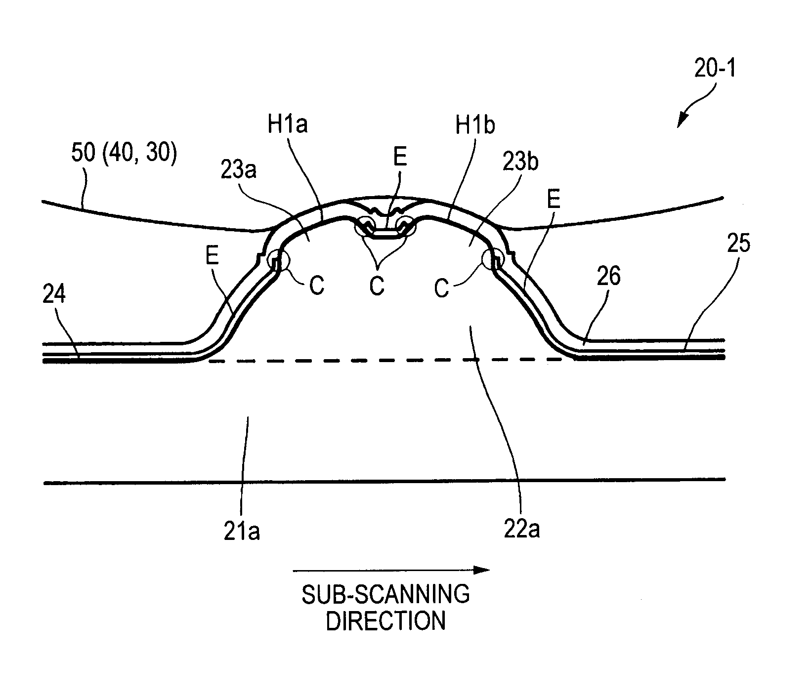
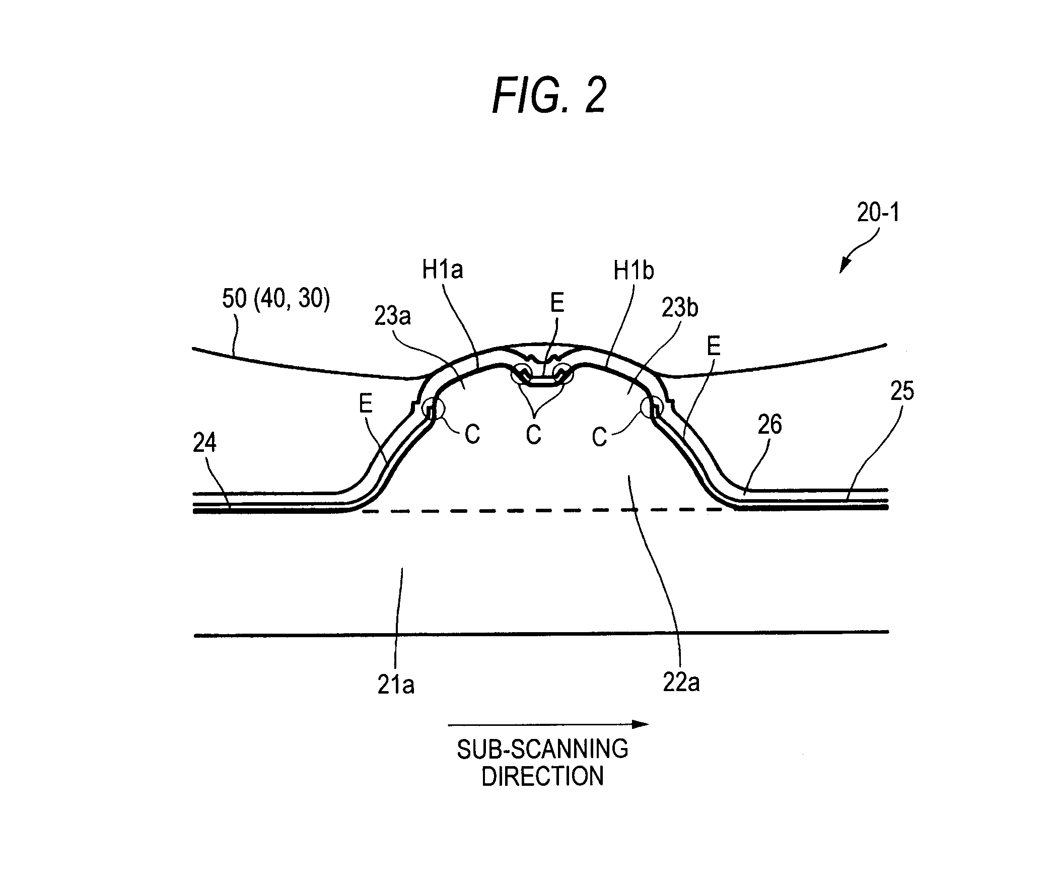
[0079]FIG. 2 is a sectional view in the sub-scanning direction showing a thermal head 20-1 according to a first embodiment of the present invention.
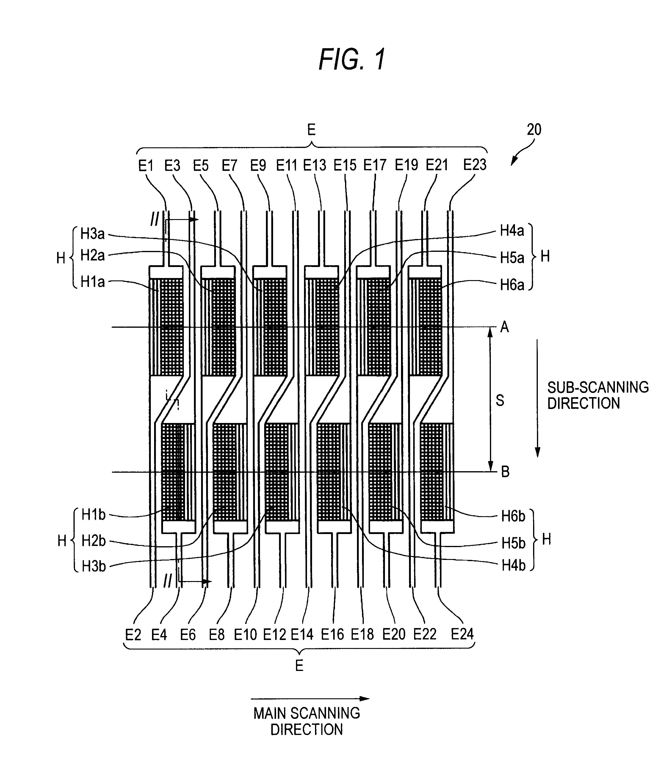
[0080]As shown in FIG. 2, in the thermal head 20-1 according to the first embodiment, a glaze 21a made of glass is formed on a substrate of alumina ceramics (not shown). The glaze 21a includes a ridge portion 22a of a ridge shape (a semicircular shape) in a section in the sub-scanning direction. On an upper side of the ridge portion 22a, plural (two) convex portions 23a and 23b arranged in the sub-scanning direction in association with the number of arrays (two rows) of the heat element row Ha and the heat element row Hb (see FIG. 1) are formed.
[0081]A resistance material layer 24 and an aluminum layer 25 are sequentially stacked on upper sides of the convex portions 23a and 23b to form the heat element H1a, the heat element H1b, and the respective electrodes E. A protective film 26 is formed to cover the heat element H1a, the heat eleme...
second embodiment
[0106]FIG. 6 is a sectional view in the sub-scanning direction showing a thermal head 20-2 according to a second embodiment of the present invention.
[0107]As shown in FIG. 6, a glaze 21b in the thermal head 20-2 according to the second embodiment is partially divided in the sub-scanning direction in association with the number of arrays (two rows) of the heat element row Ha and the heat element row Hb (see FIG. 1). The glaze 21b includes plural (two) partial ridge portions 22b and 22c of a ridge shape in sections thereof in the sub-scanning direction. The heat element H1a and the heat element H1b are arranged on upper sides of the partial ridge portion 22b and the partial ridge portion 22c.
[0108]As described above, in the thermal head 20-2 according to the second embodiment, the glaze 21b is partially divided into two near the top thereof. The partially divided portions are formed in a partial two-ridge shape in which sections of two ridges in the sub-scanning direction are semicir...
third embodiment
[0123]FIG. 9 is a sectional view in the sub-scanning direction showing a thermal head 20-3 according to a third embodiment of the present invention.
[0124]As in the thermal head 20-2 according to the second embodiment shown in FIG. 6, in the thermal head 20-3 according to the third embodiment shown in FIG. 9, the heat element H1a and the heat element H1b are arranged on the upper sides of the partial ridge portion 22b and the partial ridge portion 22c, respectively. However, a step of a protective film 27 is set small.
[0125]The step of the protective film 27 is set small to eliminate a problem of “sticking” and the like. In the thermal head 20-2 according to the second embodiment shown in FIG. 6, a step due to the thickness of the aluminum layer 25 occurs on the surface of the protective film 26 (see FIG. 6). When this step is large, the ink ribbon 50 and the recording sheet 40 heated by the heat element H1a and the heat element H1b are caught on the step and conveyed while being cau...
PUM
| Property | Measurement | Unit |
|---|---|---|
| size | aaaaa | aaaaa |
| width | aaaaa | aaaaa |
| temperature | aaaaa | aaaaa |
Abstract
Description
Claims
Application Information