Pump structure of electric integrated hydraulic brake device

Inactive Publication Date: 2016-09-22
MANDO CORP
View PDF6 Cites 4 Cited by
  • Summary
  • Abstract
  • Description
  • Claims
  • Application Information

AI Technical Summary

Benefits of technology

[0016]To solve the above described problems, the present invention provides a pump structure of an electric integrate

Problems solved by technology

Such a conventional vacuum brake needs to be supplied with a suction pressure of a vehicle engine to make a vacuum for a vacuum booster, and therefore, there is a problem in that a fuel efficiency decreases.
Further, when a vehicle stops, there is a problem in that an engine should be always driven to make a vacuum.
Since the fuel cell car and the

Method used


Image

  • Pump structure of electric integrated hydraulic brake device
  • Pump structure of electric integrated hydraulic brake device
  • Pump structure of electric integrated hydraulic brake device

Examples


Embodiment Construction

[0033]Hereinafter, exemplary embodiments of a pump structure of an electric integrated hydraulic brake device according to the present invention will be described in detail with reference to the accompanying drawings. First, when reference numerals are assigned to elements of each drawing, if the same elements are illustrated in different drawings, the same reference numerals are assigned to the same elements whenever possible. Also, in descriptions of the present invention, when detailed descriptions of related known configurations or functions are deemed to unnecessarily obscure the gist of the present invention, they will be omitted.

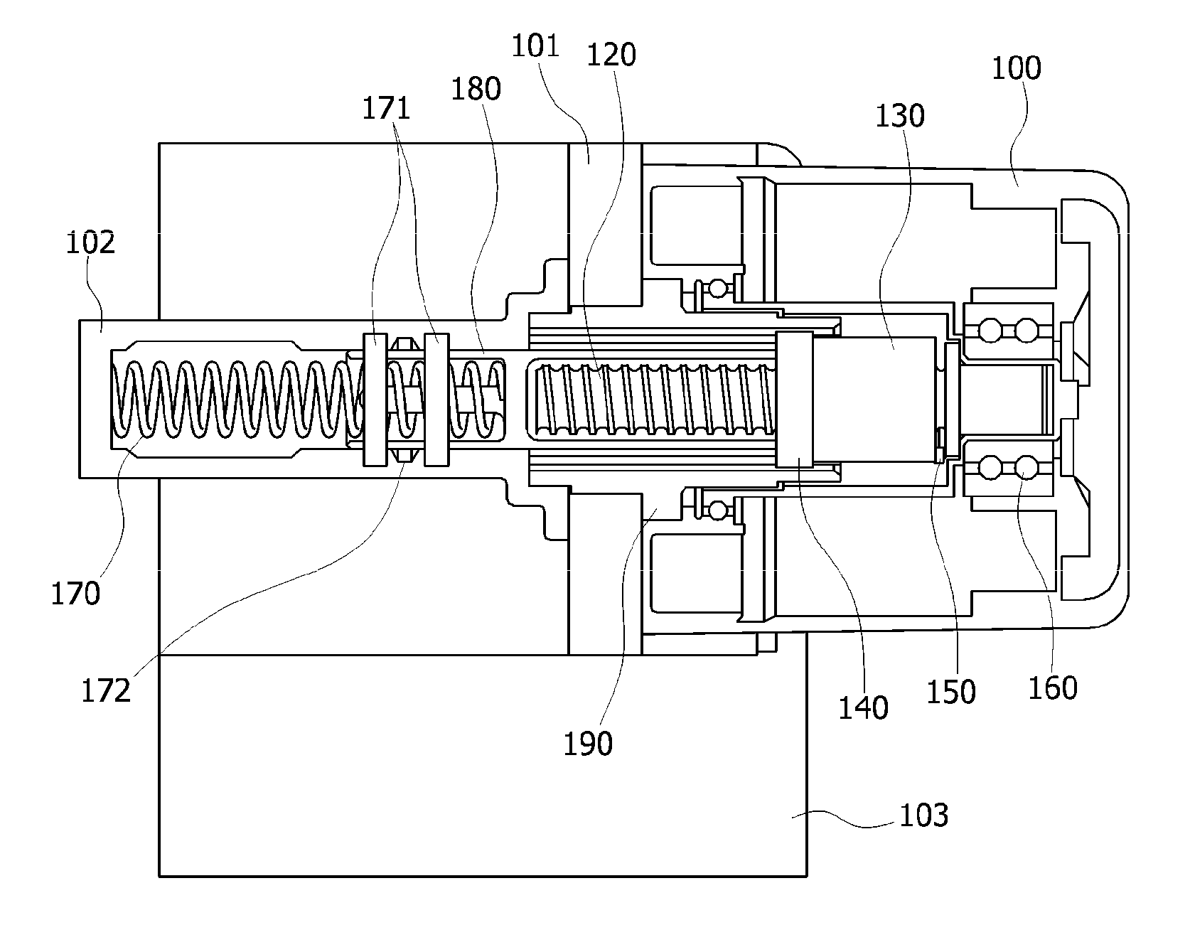
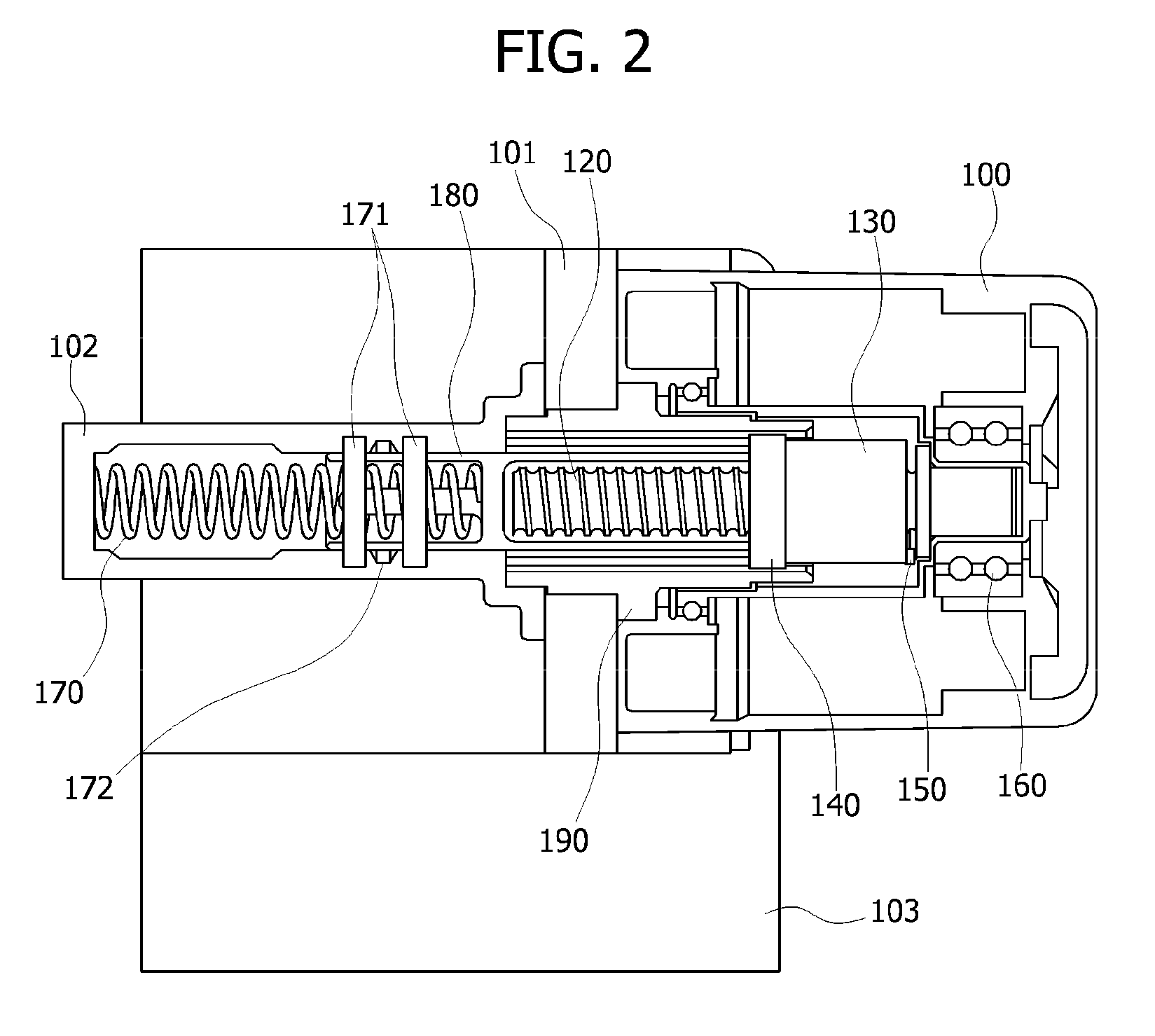
[0034]Before a description of the pump structure of an electric integrated hydraulic brake device according to an embodiment of the present invention, the electric integrated hydraulic brake device will be described with reference to FIG. 2. FIG. 2 is a schematic view illustrating the electric integrated hydraulic brake device.

[0035]The electric integ...


PUM


Abstract

The present invention relates to a pump structure of an electric integrated hydraulic brake device, and more particularly, to a pump structure of an electric integrated hydraulic brake device, which is applied to an inside of a motor having a hollow. The pump structure of an electric integrated hydraulic brake device includes a motor (100) provided with a hollow, a ball screw (120) provided inside the hollow and connected and rotated with a rotor of the motor (100), a ball nut (130) provided inside the hollow, connected with the ball screw (120), and moved in a reciprocal direction according to a rotational direction of the ball screw (120), a guide (140) provided inside the hollow, provided at one end portion of the ball nut (130) and configured to press an adjacent piston (180), and a supporter (150) formed in one end portion of the ball screw (120) to rotate together with the ball screw (120), and provided opposite the other end portion of the ball nut (130).

Description

CROSS-REFERENCE TO RELATED APPLICATION[0001]This application claims priority to and the benefit of Korean Patent Application No. 10-2015-0039438, filed on Mar. 21, 2015, the disclosure of which is incorporated herein by reference in its entirety.BACKGROUND[0002]1. Field of the Invention[0003]The present invention relates to a pump structure of an electric integrated hydraulic brake device, and more particularly, to a pump structure of an electric integrated hydraulic brake device, which is applied to an inside of a motor having a hollow.[0004]2. Discussion of Related Art[0005]Recently, a hybrid car, a fuel cell car, an electric car and the like have been actively developed to enhance a fuel efficiency and reduce an exhaust gas. These vehicles are necessarily equipped with a brake device, wherein the brake device for a vehicle is a device to decrease the speed of a running vehicle and to halt the vehicle.[0006]Conventionally, there are a vacuum brake to generate a braking force using...

Claims


Application Information

Patent Timeline
IPC IPC(8): B60T13/16F04B17/03F04B19/22F16H25/22
CPCB60T13/16F16H25/2204F04B19/22F04B17/03B60T13/161B60T13/745B60T7/042B60T13/166B60T13/662B60T13/686F04B9/047B60T8/368B60T8/4081F16H35/18F16H2025/204F16H2025/2075
Inventor LEE, YOUNG SONG
Owner MANDO CORP
Why Eureka
Try Eureka