
Metal mold for vulcanizing tire treads

a metal mold and tire technology, applied in the field of vulcanizing metal molds, can solve the problems of lowering the venting effect, affecting the appearance of the obtained tires, and often remaining in the vent holes of the cut-off tire, so as to prevent incorrect assembly of a plurality of split pieces. , the effect of easy and quick assembly

Inactive Publication Date: 2010-03-02
TOYO TIRE & RUBBER CO LTD
View PDF7 Cites 11 Cited by
  • Summary
  • Abstract
  • Description
  • Claims
  • Application Information

AI Technical Summary

Benefits of technology

[0011]To solve the above problems, it is an object of the present invention to provide a metal mold for vulcanizing tire treads, which, after having been washed, can be easily and quickly assembled reliably preventing incorrect assembling of a plurality of split pieces.
[0012]In order to achieve the above object, the present inventors have conducted a keen study, have discovered that incorrect assembling can be prevented by providing the contact surfaces of pairs of pieces with protuberances and corresponding dents, respectively, and have finished the present invention.

Problems solved by technology

Besides, the spews that are cut often remain in the vent holes.
Even with the metal mold split into the pieces, however, the rubber adheres on the surfaces of the metal mold and in the air-venting gaps among the pieces like the ordinary metal mold for vulcanizing the tires after the tires are vulcanize-molded several hundreds to several thousands of times, impairing the appearance of the obtained tires and lowering the venting effect, still requiring the washing of the metal mold at regular intervals.
At the time of assembling the metal mold after the washing, therefore, the split pieces must be very carefully arranged to prevent incorrect assembling, which is a time-consuming work.
Further, according to JP-A-7-314459, the pieces can be positioned, but incorrect assembling cannot be confirmed until after the pieces are set in the casing.
Besides, limitation is imposed on the direction for inserting the pieces in the casing, still leaving room for improvement.

Method used


Image

  • Metal mold for vulcanizing tire treads
  • Metal mold for vulcanizing tire treads
  • Metal mold for vulcanizing tire treads

Examples


Embodiment Construction

[0022]An embodiment of the invention will now be described with reference to the drawings.

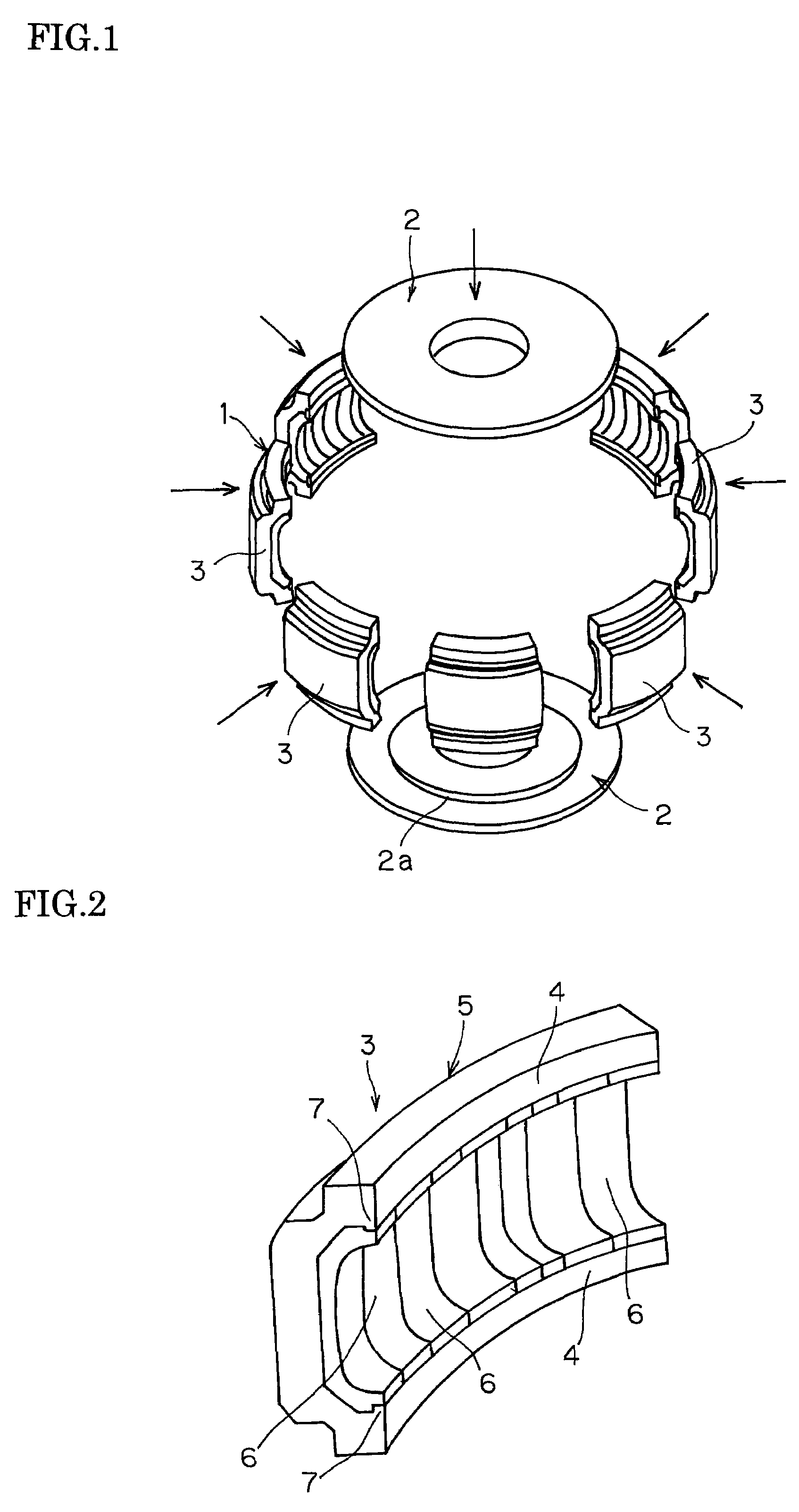
[0023]FIG. 1 is a perspective view schematically illustrating a metal mold for vulcanizing a tire tread together with a pair of side metal molds for vulcanization according to an embodiment of the present invention, wherein reference numeral 1 denotes a metal mold for vulcanizing a tire tread according to the invention, and reference numeral 2 denotes a pair of side metal molds for vulcanization.

[0024]The metal mold 1 for vulcanizing the tire tread comprises a plurality of (eight in the drawing) sector molds 3 which can be horizontally moved in the radial direction so as to expand or contract. Adjacent sector molds 3 closely adhere to each other. When contracted in diameter, therefore, the sector molds 3 as a whole constitute a circular shape and, in the drawing, work to vulcanize and mold a raw tire together with the pair of upper and lower side metal molds 2 for vulcanization, thereby to form...


PUM

PropertyMeasurementUnit
degree of freedomaaaaaaaaaa
circumferential lengthaaaaaaaaaa
timeaaaaaaaaaa

Abstract

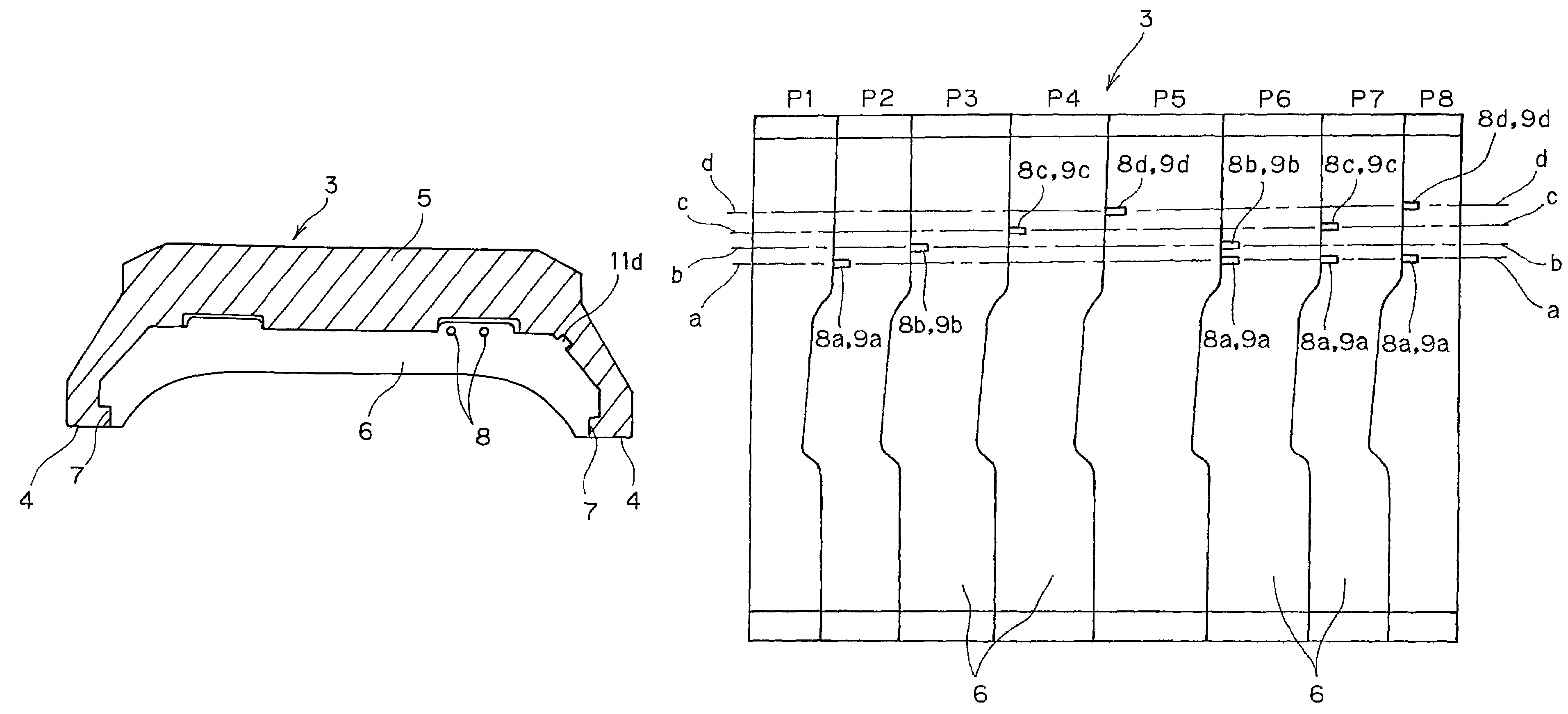
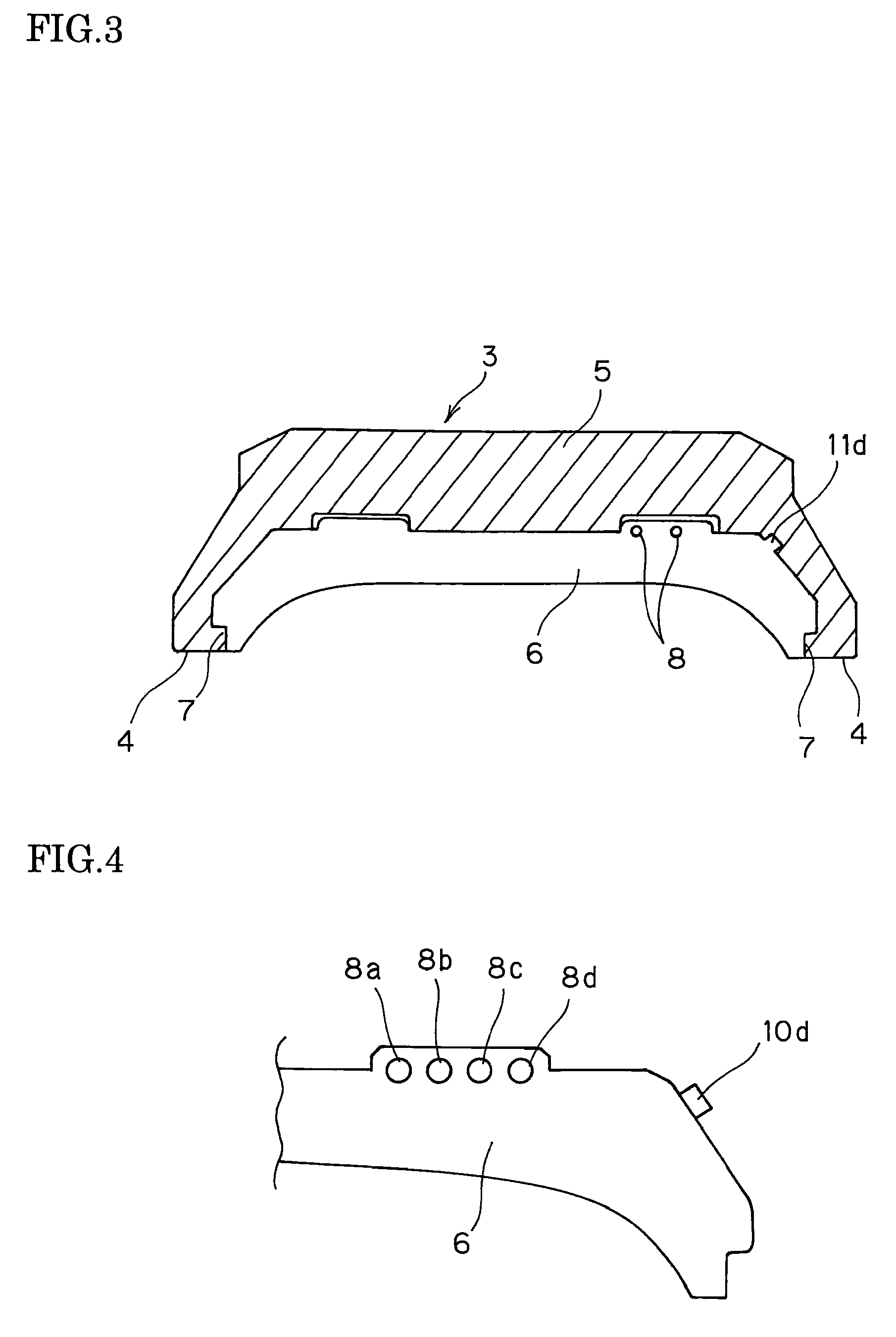
A metal mold for vulcanizing tire treads reliably preventing incorrect assembling of split pieces. The metal mold 1 for vulcanizing tire treads to form a tread of a tire, comprises a plurality of sector molds 3 equipped with a plurality of pieces 6 which are arranged on the inner circumferential surface of a casing 5 and are split in the circumferential direction in which a tread pattern of the tire is formed, wherein among the adjacent pieces 6 in the sector molds 3, a protuberance 8 is formed on the contact surface of the one piece 6, a dent 9 corresponding to the protuberance 8 is formed in the contact surface of the another piece 6, and the positions for forming the protuberance 8 and the dent 9 are differed for each of the adjacent pieces 6 in the sector molds 3.

Description

BACKGROUND OF THE INVENTION[0001]1. Field of the Invention[0002]This invention relates to a vulcanizing metal mold for vulcanizing and molding raw tires and, specifically, to a metal mold for vulcanizing tire treads, which is constituted by a plurality of sector molds for molding treads of tires. More particularly, the invention relates to a metal mold for vulcanizing tire treads, capable of preventing incorrect assembling of a plurality of pieces attached to a casing for molding a tread pattern.[0003]2. Description of the Related Art[0004]A metal mold of the type split in the circumferential direction has heretofore been known as a metal mold for vulcanizing the tires. The metal mold of this type is provided with many apertures called vent holes for venting the air communicated with the interior and exterior of the metal mold to discharge a gas such as the air trapped between the metal mold and the raw tire out of the metal mold while the tire is being vulcanized. However, the vent...

Claims


Application Information

Patent Timeline
Patent Type & Authority Patents(United States)
IPC IPC(8): B29C35/02
CPCB29D30/0629
Inventor HYODO, MASAKI
Owner TOYO TIRE & RUBBER CO LTD
Learn More