

Terminal fitting
a technology of terminals and fittings, applied in the field of terminal fittings, can solve the problems that the deformation stabilizer may not provide sufficient locking force on the terminal, and achieve the effects of preventing deformation, improving yield, and preventing the movement of the stabilizer
- Summary
- Abstract
- Description
- Claims
- Application Information
AI Technical Summary
Benefits of technology
Problems solved by technology
Method used
Image

Examples
first embodiment
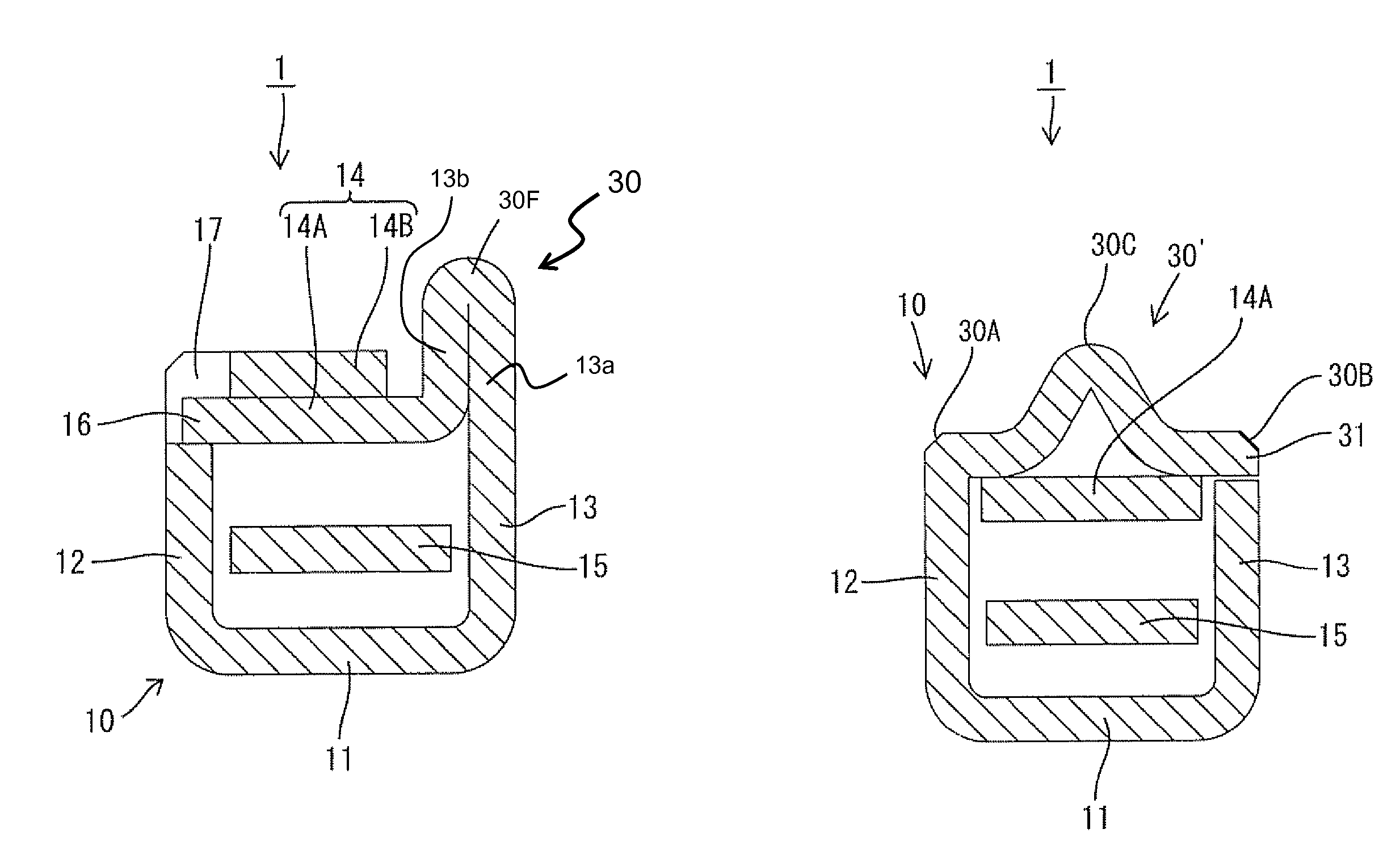
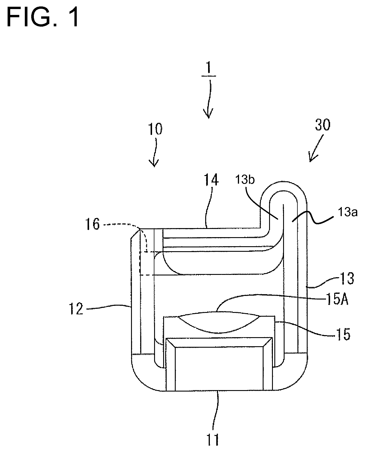
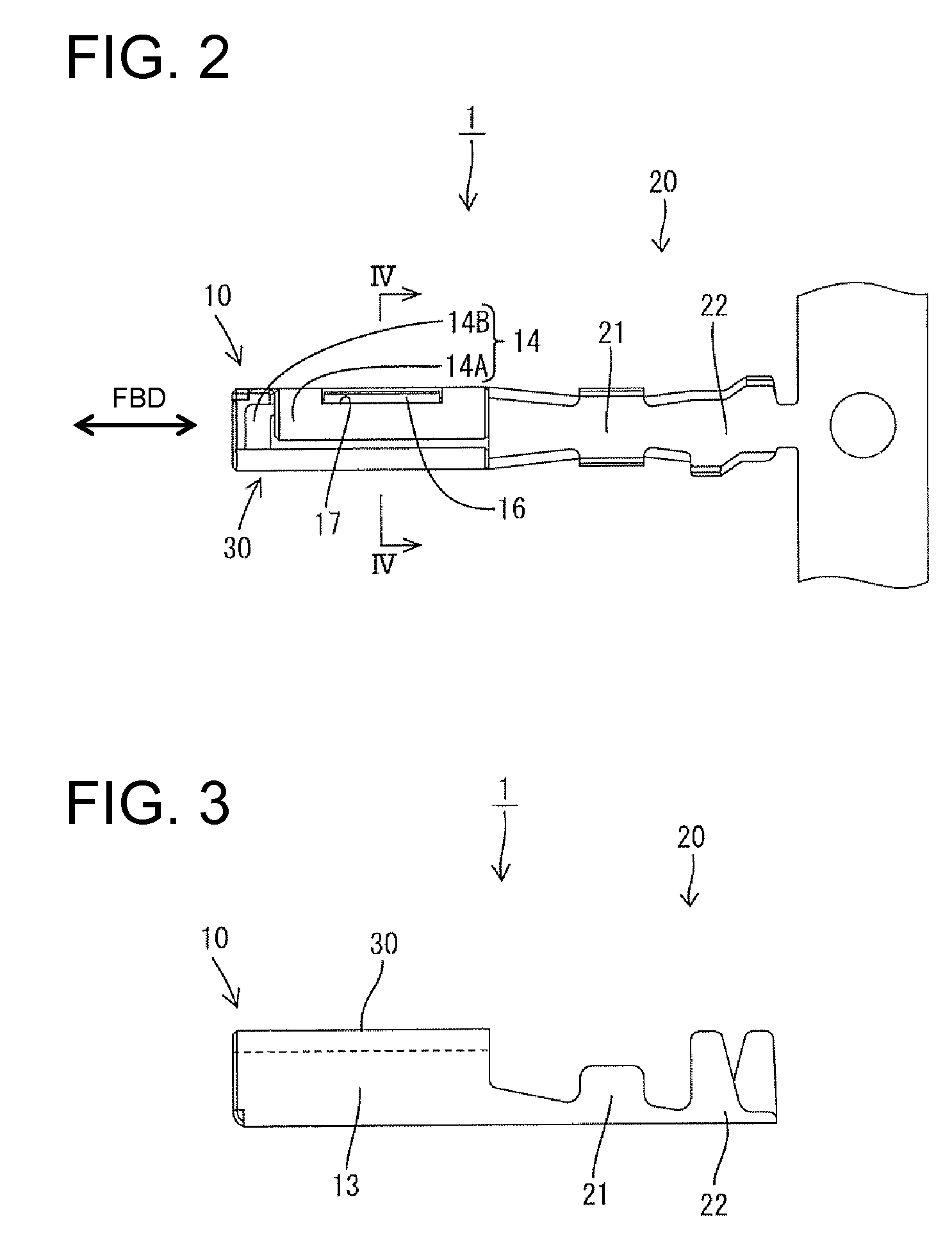
[0030]A terminal fitting in accordance with the invention is identified by the numeral 1 in FIGS. 1 to 5. The terminal fitting 1 of this embodiment has a substantially rectangular tubular main portion 10 that extends in forward and backward directions FBD. A wire connection barrel 20 is continuous with the rear end of the main portion 10 and a stabilizer 30 is formed at an outer corner of the main portion 10. In the following description, reference is made to FIG. 1 concerning vertical and lateral directions.
[0031]The barrel portion 20 includes a wire barrel 21 to be crimped, bent or folded into connection with a core of a wire end (not shown) and an insulation barrel 22 to be crimped, bent or folded into connection with an insulated part of the wire end, such as a wire coating. The insulation barrel 22 is behind the wire barrel 21 and includes crimping pieces displaced from each other in forward and backward directions FBD.
[0032]As shown in FIG. 1, the main portion 10 is comprised ...
second embodiment
[0056]A terminal fitting in accordance with the invention is illustrated FIGS. 7 to 11. The terminal fitting 1 of this embodiment has a rectangular tubular main portion 10 that extends in forward and backward directions FBD. A wire connection portion 20 is continuous with the rear end of the main portion 10 and a stabilizer 30′ projects from the main portion 10. The stabilizer 30′ can be inserted into an insertion groove (not shown) formed in an inner surface of a cavity (not shown) to guide the main portion 10 into the cavity. In the following description, reference is made to FIG. 7 concerning vertical and lateral directions.
[0057]The wire connection portion 20 includes a wire barrel 21 to be crimped, bent or folded into connection with a core of a wire end (not shown) and an barrel portion 22 to be crimped, bent or folded into connection with an insulated part of the wire end. The insulation barrel 22 is arranged behind the wire barrel 21 and includes two crimping pieces displace...
PUM
 Abstract
Description
Claims
Application Information