User guidance in adjusting bone incision blocks

a bone incision block and user technology, applied in the field of user guidance in adjusting the bone incision block, can solve the problem of not being able to intuitively predict the effect, and achieve the effect of saving tim

Active Publication Date: 2010-03-02
BRAINLAB
View PDF10 Cites 149 Cited by
  • Summary
  • Abstract
  • Description
  • Claims
  • Application Information

AI Technical Summary

Benefits of technology

[0009]An advantage of the invention is that the spatial position of the adjustment device can be determined such that the user is provided with the actual incision plane (e.g., the plane defined by the incision guide), the target incision plane (e.g., the target plane as determined by the navigation system), the difference between the two, and instructions as to how he can set the actual incision plane to correspond with the target incision plane (e.g., instructions on how to manipulate the adjustment device). This user guidance can be used in all possible arrangements of the incision block around the bone, and can save time and yet allow the incision plane to be set exactly.
[0010]The adjustment device can include setting media (also referred to as a setting device) by means of which the incision guide can be rotated around two non-parallel axes and adjusted in height. One setting medium, e.g., hand wheel screw setting devices, can be provided for each degree of freedom.
[0011]The registration element can include an at least puncticular reference arranged fixed to the adjustment device. It is possible to arrange the reference of the adjustment device at a location characteristic of the individual bone incision block. The possibility also exists of arranging the reference of the adjustment device at a preset distance from the localization reference or, for various configurations (various arrangements of the incision guide with respect to the adjustment device), at a defined presettable distance from the localization reference.
[0012]The reference can be a depression at a point on the surface of the adjustment device, e.g., a “one-dimensional” puncticular reference. In the registration process, a navigated pointer, for example, can be moved to such a depression to determine its position (navigation system).
[0013]The reference also can have a two-dimensional extent and, in particular, can be a bore at a point on the adjustment device or can have two depressions on the surface of the adjustment device, wherein the spatial position of the two-dimensional elements can be detected in the registration process using a navigated pointer.
[0014]In another embodiment, the spatial position of the adjustment device can be set, predetermined with respect to the localization reference, wherein a locking interface provided between the adjustment device (including its registration element) and the incision guide (including its localization reference) only allows defined relative positions of the two elements, the corresponding information being stored in the navigation system.

Problems solved by technology

If the incision block arrangement is unfavorable, the user, without guidance, cannot intuitively predict the effect that a particular manipulation of the adjustment device will have on the resulting incision plane.

Method used


Image

  • User guidance in adjusting bone incision blocks
  • User guidance in adjusting bone incision blocks
  • User guidance in adjusting bone incision blocks

Examples


first embodiment

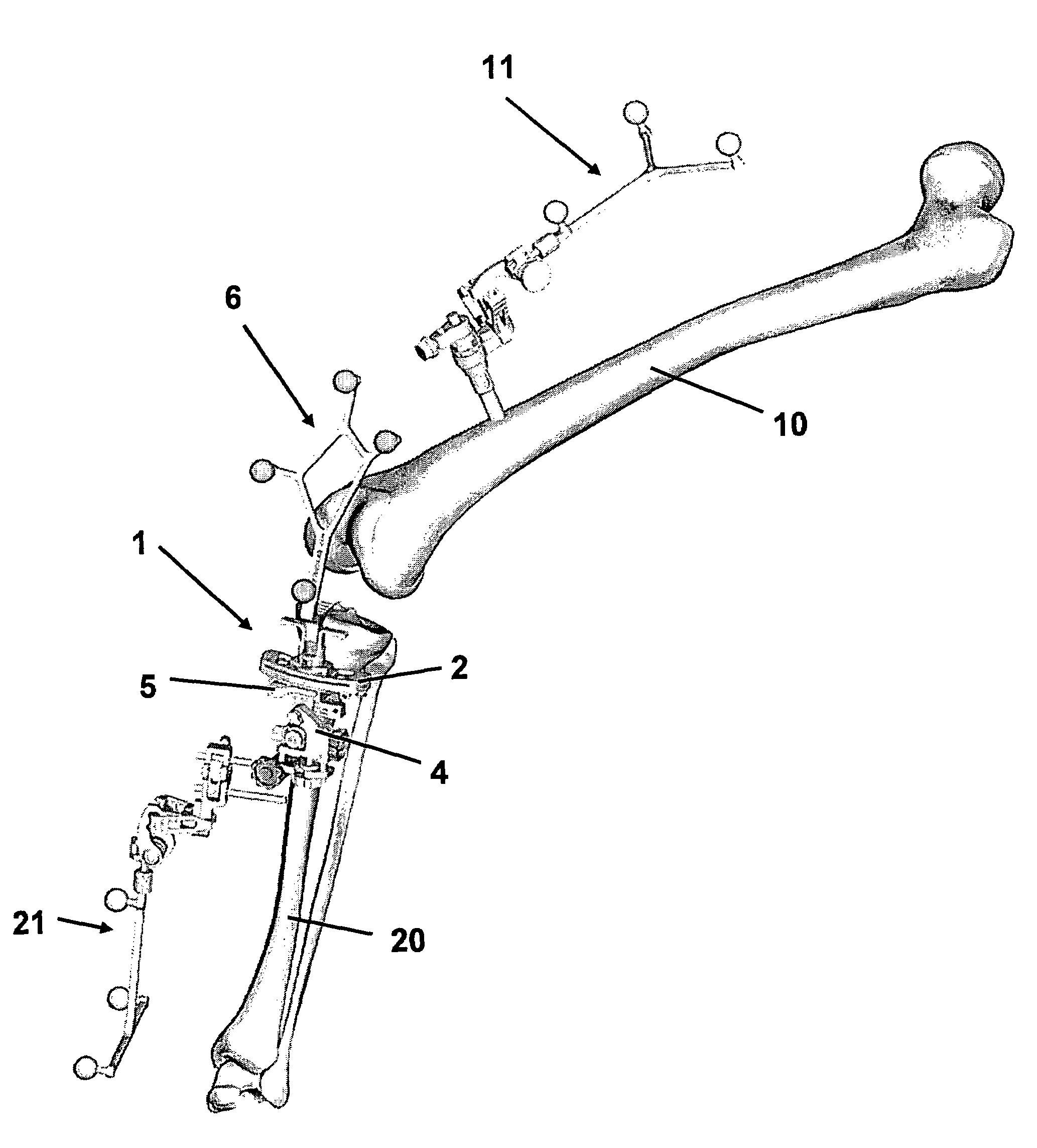
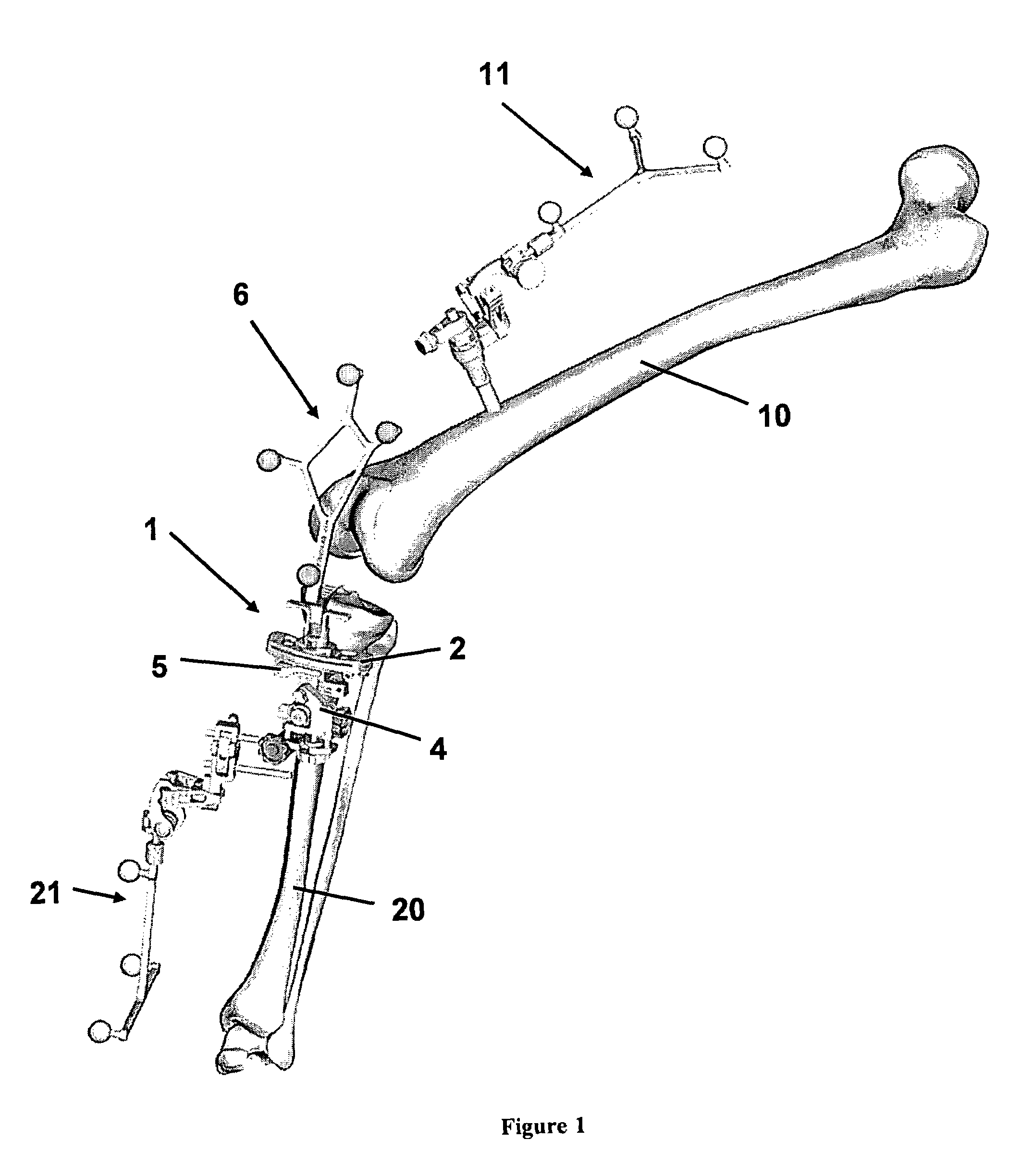
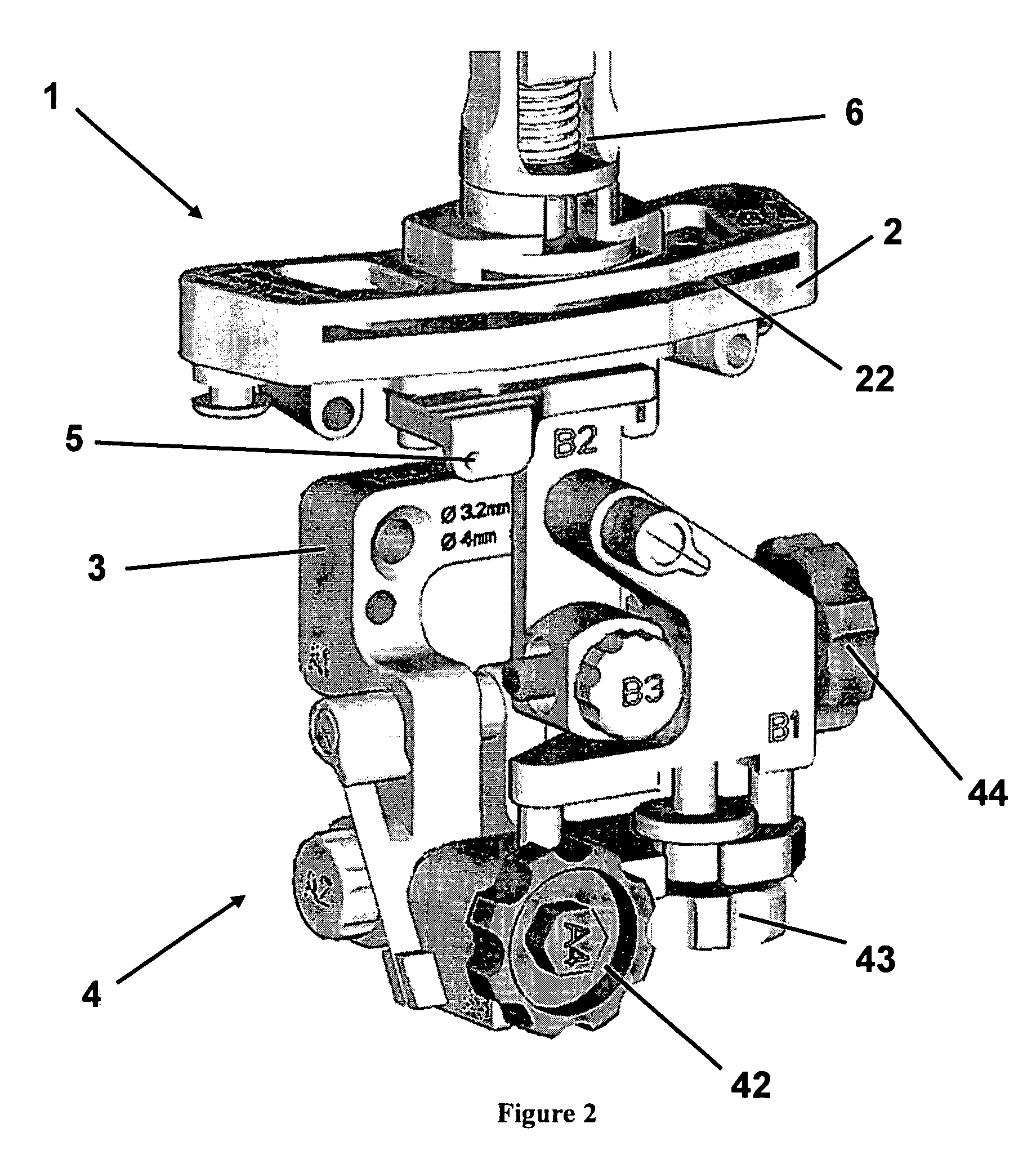
[0037]In order to provide user guidance, it is necessary to know the spatial position of the adjustment device 4 (especially with respect to the bone to be treated). In a first embodiment, this purpose is served by the registration point 5, which is embodied as a depression at the top end of the adjustment device 4. The tip of a navigable pointer, for example, can be inserted into such a depression to determine the spatial position of the depression 5 (and therefore the adjustment device 4) using the navigation system. The information thus obtained, combined with the information on the position of the localization reference 6, is sufficient to determine the position of the adjustment device on the bone. Based on this information, instructions for the setting process (i.e., for reaching the target incision plane) are derived.

[0038]The adjustment device 4 has three hand wheels 42, 43 and 44 using which the incision guide 2 can be tilted around two non-parallel axes and adjusted in hei...

second embodiment

[0045]FIG. 9 shows the incision block, wherein a two-dimensional registration element 5 is provided. The two-dimensional registration element 5 is useful when pre-defined configurations between the adjustment device 4 and the incision guide 2 are not provided or not possible. In such situations, correlations via characteristic distances 7 and angular relationships (which are stored in the database) cannot be performed. Using two-dimensional registration elements allows the incision guide 2 to move freely within the incision plane, wherein the information regarding the incision plane is provided as usual to the navigation system via the localization reference 6. Additionally, the position of the adjustment device on the bone is determined with the aid of the two-dimensional registration element 5 (e.g. two points or a bore forming the normal vector of a plane).

[0046]FIG. 10 shows the registration process of an incision block 1 including a registration element 5, which in the present ...


PUM


Abstract

A bone incision block includes an incision guide, a localization reference adjustably attached to the incision guide, a fastener for fastening to a bone, and an adjustment device. The incision guide defines an incision plane, and the localization reference enables the incision plane to be spatially determined. The adjustment device is operatively coupled between the fastener and the incision guide, wherein the incision plane can be set relative to the bone via the adjustment device, and a spatial position of the adjustment device can be determined via a registration element.

Description

RELATED APPLICATION DATA[0001]This application claims priority of U.S. Provisional Application No. 60 / 655,584 filed on Feb. 23, 2005, which is incorporated herein by reference in its entirety.FIELD OF THE INVENTION[0002]The invention relates to adjusting bone incision blocks and, more particularly, to a system and method for guiding a user in adjusting the bone incision block.BACKGROUND OF THE INVENTION[0003]In computer-assisted knee arthroplasty, for example, an incision block is commonly used, wherein the incision block includes an incision guide for defining an incision plane. A localization reference is attached to the incision guide, wherein the localization reference can be spatially adjusted, e.g., rotated, in order to allow the localization reference to be optimally visible for various applications and / or configurations. By means of the localization reference and a medical navigation system, an attempt is made to position the incision block such that the incision guide comes...

Claims


Application Information

Patent Timeline
Patent Type & Authority Patents(United States)
IPC IPC(8): A61F2/00
CPCA61B17/154A61B17/157A61B19/50A61B19/5244A61B19/56A61B2019/444A61B2019/5255A61B2019/5268A61B2019/527A61B2019/5483A61B2090/3983A61B2034/2055A61B2034/2068A61B2034/207A61B34/20A61B34/25A61B90/92A61B34/10
Inventor PLASSKY, NORMANNEUBAUER, TIMOBRACK, CHRISTIANGOTTE, HUBERT
Owner BRAINLAB
Why Eureka
Try Eureka