Eureka AIR delivers breakthrough ideas for toughest innovation challenges, trusted by R&D personnel around the world.

Display

a technology of display and backlight, applied in the field of display, can solve the problem that the backlight does not provide uniform illumination over the area of the spatial light modulator (slm), and achieve the effect of low brightness and low observer head freedom

Inactive Publication Date: 2010-03-02
SHARP KK
View PDF10 Cites 32 Cited by
  • Summary
  • Abstract
  • Description
  • Claims
  • Application Information

AI Technical Summary

Benefits of technology

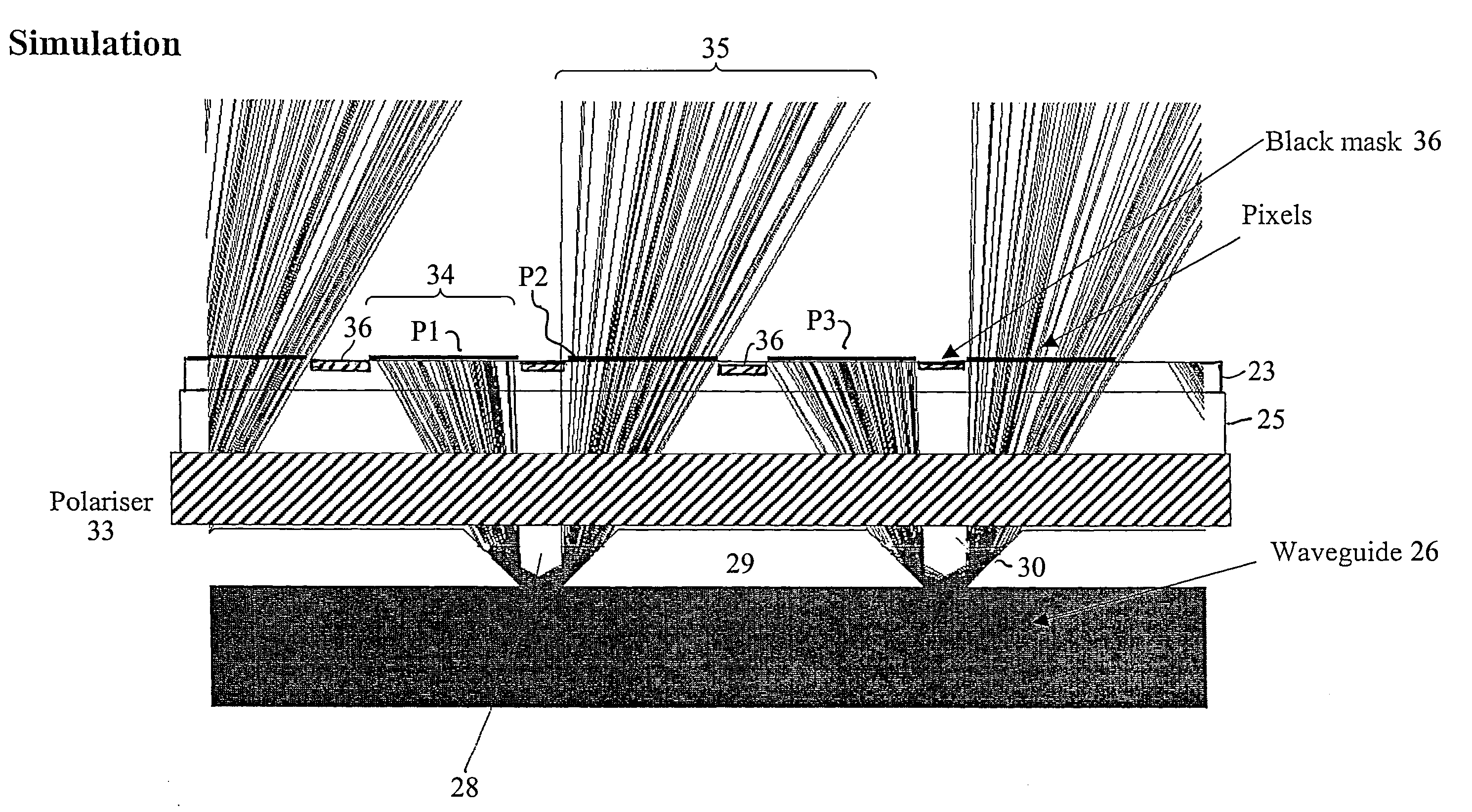
[0020]A first aspect of the present invention provides a display comprising: a transmissive pixellated spatial light modulator; and a backlight; wherein the backlight has a light-transmissive waveguide, a first face of the waveguide being opposed to the spatial light modulator; wherein the first face of the waveguide comprises a plurality of regions that are not totally internally reflective for at least one polarisation of light propagating within the waveguide, the remainder of the first face of the waveguide being totally internally reflective for light propagating within the waveguide; and wherein the pitch of the regions is substantially an integer multiple of the pitch of the pixels of the spatial light modulator. The regions of the backlight where the first face of the waveguide is totally internally reflective appear dark, and the backlight does not provide uniform illumination over the area of the spatial light modulator (SLM). The variation in intensity, over the area of the backlight, allows directional display of two images without the need for a parallax barrier. A parallax barrier is therefore not needed in a display of the invention, and the problems arising from the presence of a parallax barrier such as low brightness and low observer head freedom are therefore alleviated.
[0034]The shape of the light-directing surfaces of a protrusion may be dependent upon the distance of the protrusion from a side edge of the waveguide. This can compensate for the decrease in intensity of light propagating in the waveguide with an increase in distance from a light source.
[0067]The image display layer may be a pixellated image display layer; and a plurality of regions where the interface between the structure and the waveguide is not totally internally reflective for at the least one polarisation of light may be provided behind each pixel aperture of the image display layer. This provides uniform, high intensity illumination of each pixel.
[0068]The structure may be provided between the image display layer and the waveguide. The surface where light is extracted from the waveguide is then disposed close to the image display layer, allowing good registration between the light extraction points and the image display layer.
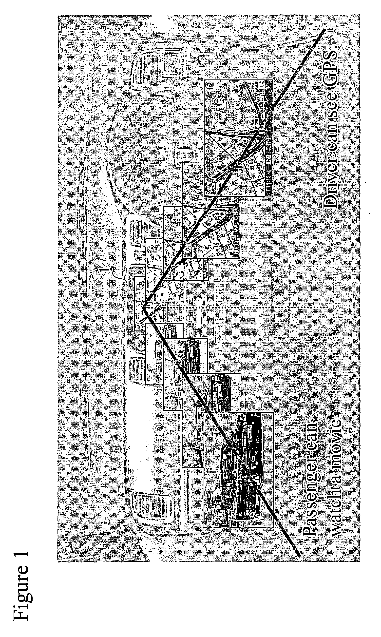
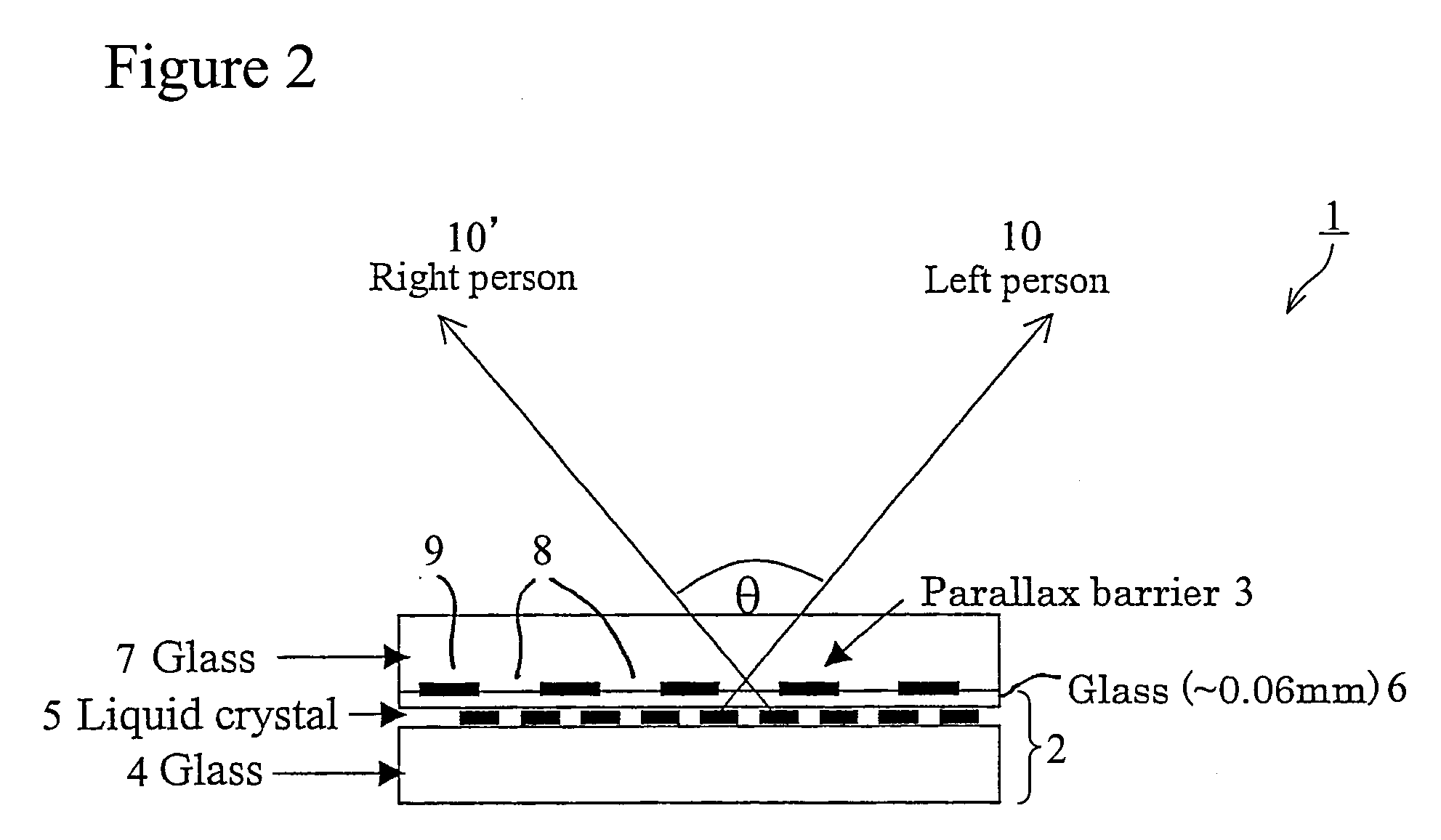
[0070]A display according to this aspect can again provide a directional display without the need for a parallax barrier to be provided, since the reflective louvres direct light from the SLM into two viewing windows. Problems arising from the presence of a parallax barrier, such as low brightness and low observer head freedom, are again alleviated.

Problems solved by technology

The regions of the backlight where the first face of the waveguide is totally internally reflective appear dark, and the backlight does not provide uniform illumination over the area of the spatial light modulator (SLM).

Method used


Image

  • Display
  • Display
  • Display

Examples


second embodiment

[0164]FIG. 8A is a schematic plan sectional view through a display 38 according to the present invention. The display 38 again comprises a transmissive spatial light modulator 21 disposed in front of a backlight 22. The SLM 21 may be any conventional SLM, and will not be described in detail. It will be assumed for the purpose of description that the SLM 21 comprises a liquid crystal layer, but the invention is not limited to this.

[0165]The backlight again comprises a waveguide 26 that is illuminated by one or more light sources 27 disposed along respective side edges of the waveguide 26. Most of the exit face of the light guide 26 is totally internally reflective to light propagating within the waveguide, but the front face of the waveguide comprises a plurality of regions 39 that are not totally internally reflective for light propagating within the waveguide. These non-TIR regions 39 form “light extraction points” at which light is extracted from the waveguide 26.

[0166]In the disp...

third embodiment

[0175]FIG. 9 is a schematic sectional plan view of a display 40 according to the present invention. The display 40 again comprises a transmissive pixellated spatial light modulator 21 and a backlight 22 provided for illuminating the spatial light modulator 21. The display 40 corresponds generally to the display 20 of FIG. 3, and the description of components common to both displays will not be repeated.

[0176]In the display 40, a birefringent material 41 is disposed over the exit face of the waveguide 26 of the backlight at regions where it is desired that light is extracted from the waveguide 26. The birefringent material 41 is disposed immediately adjacent to the exit face of the substrate at these locations, so that the regions of the exit face of the substrate where the birefringent material 41 is provided become non-totally internally reflecting for light of a first polarisation state. This requires that the birefringent material 41 has a refractive index for light of the first ...


PUM

PropertyMeasurementUnit
angleaaaaaaaaaa
angleaaaaaaaaaa
angleaaaaaaaaaa

Abstract

A display comprises: a transmissive pixellated spatial light modulator (21); and a backlight (22). The backlight has a light-transmissive waveguide (26), with a first face of the waveguide being opposed to the spatial light modulator (21). The first face of the waveguide comprises a plurality of regions that are not totally internally reflective for at least one polarisation of light propagating within the waveguide, and the remainder of the first face of the waveguide is totally internally reflective for light propagating within the waveguide. Light is extracted from the waveguide at the regions where first face of the waveguide is not totally internally reflective. The pitch of the regions where first face of the waveguide is not totally internally reflective is substantially an integer multiple of the pitch of the pixels of the spatial light modulator.

Description

[0001]This Nonprovisional application claims priority under 35 U.S.C. § 119(a) on UK Patent Application No. 0510192.8 filed in the United Kingdom on May 19, 2005, the entire contents of which are hereby incorporated by reference.FIELD OF THE INVENTION[0002]The present invention relates to a display, in particular to a display in which light from the display is directed preferentially into two or more angular ranges. The display of the invention may display a conventional two-dimensional image, or it may be a multiple-view directional display which displays two or more images such that each image is visible from a different direction (for example so that two observers who view the display from different directions will see different images to one another).BACKGROUND OF THE INVENTION[0003]For many years conventional display devices have been designed to be viewed by multiple users simultaneously. The display properties of the display device are made such that viewers can see the same ...

Claims


Application Information

Patent Timeline
Patent Type & Authority Patents(United States)
IPC IPC(8): G02F1/1335F21V8/00G02F1/13357H04N13/00
CPCG02B6/0038G02B6/0055G02B6/0056G02F1/133615G02F1/13362H04N13/0409H04N13/0411H04N13/0418H04N13/045G02F1/133524G02B30/30H04N13/31H04N13/312H04N13/32H04N13/354
Inventor MATHER, JONATHANLESAGE, ETIENNEMONTGOMERY, DAVID JAMES
Owner SHARP KK
Why Eureka
Eureka Blog
Learn More