
Method and apparatus for adaptive load balancing

a load balancing and adaptive technology, applied in the field of networks, can solve the problems of inability to tolerate such latencies, negligible lock contention on the load balancing structure, delay in processing requests, etc., and achieve low overhead/low latency, facilitate efficient adaptive load balancing, and reduce load balancing decision-making

Active Publication Date: 2010-03-09
ORACLE INT CORP
View PDF8 Cites 23 Cited by
  • Summary
  • Abstract
  • Description
  • Claims
  • Application Information

AI Technical Summary

Benefits of technology

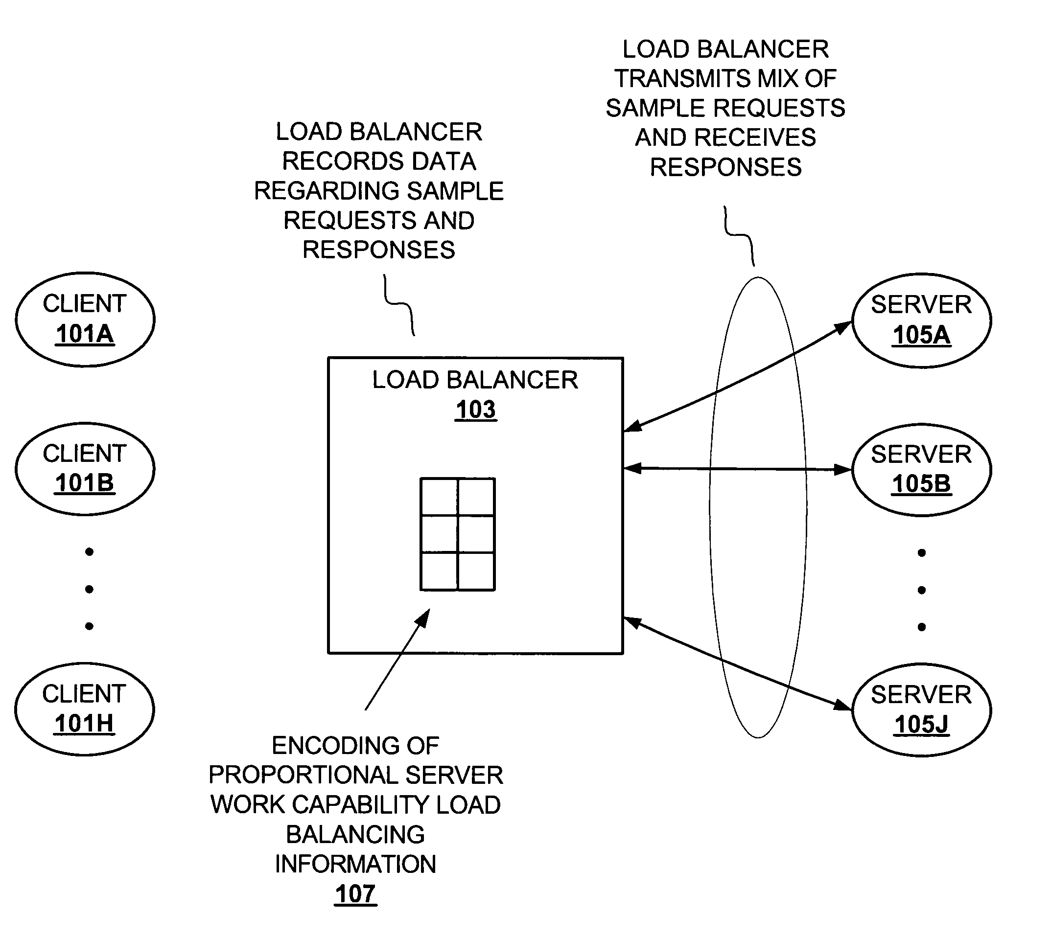
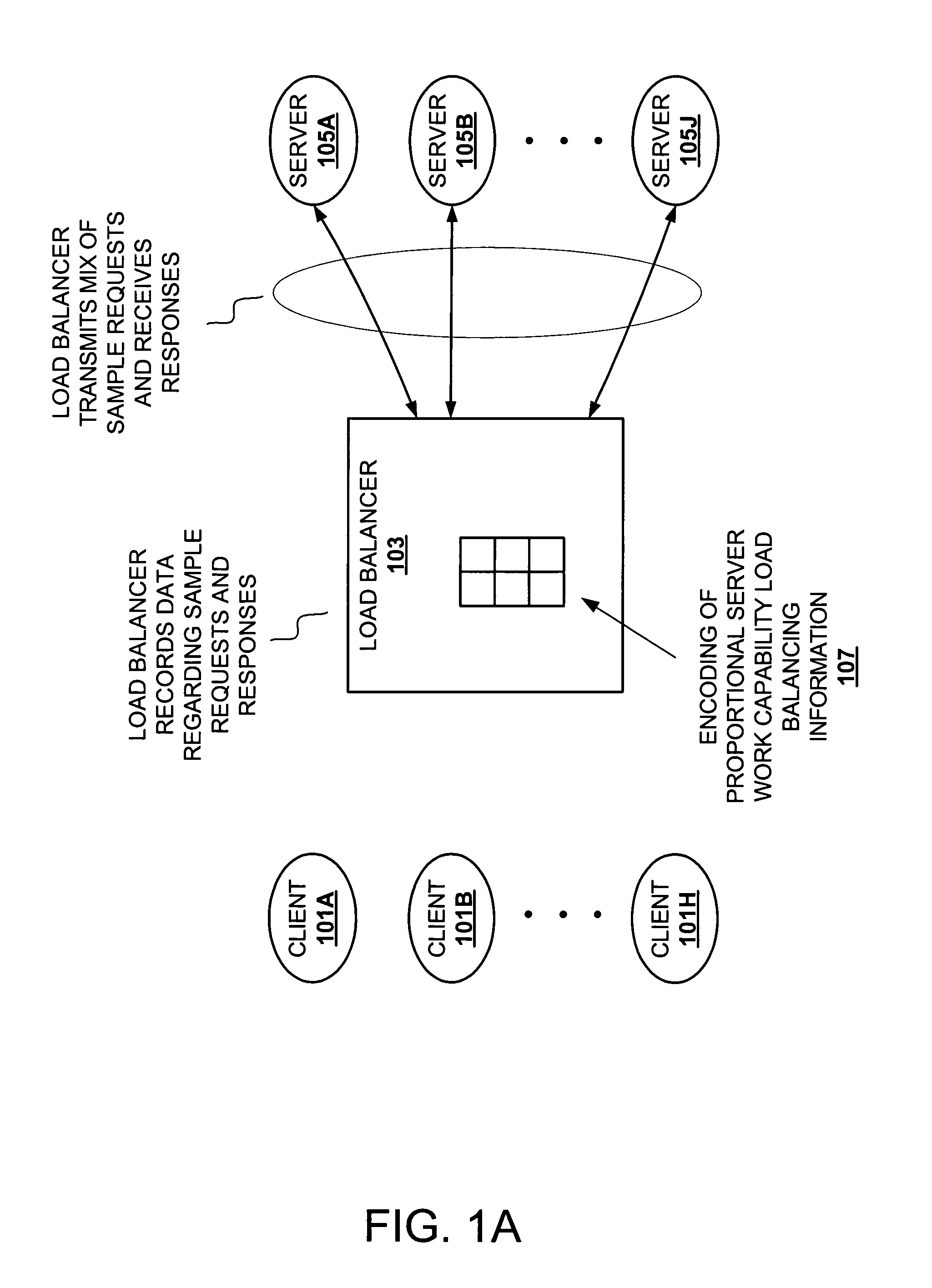
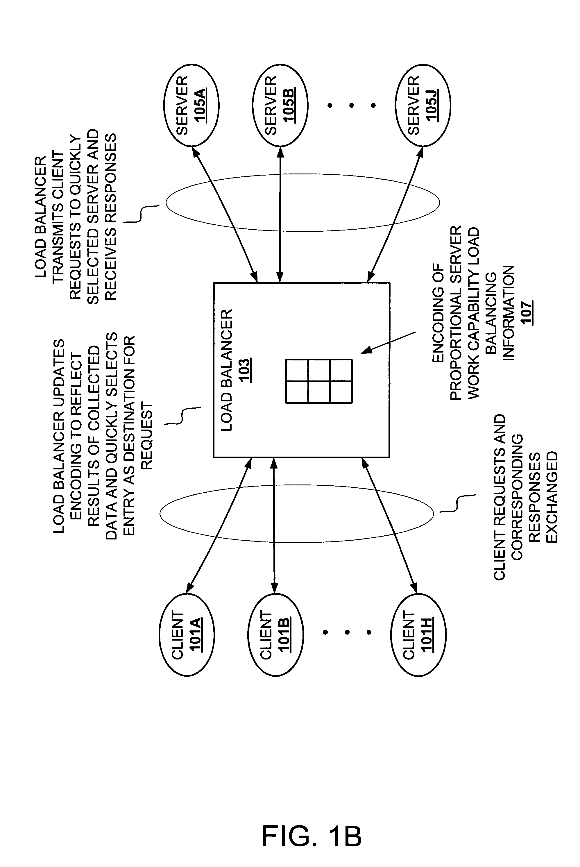
[0007]Updating load balancing information, which reflects proportional server capability, facilitates efficient adaptive load balancing. Maintained load balancing information can be utilized to perform low overhead / low-latency load balancing. Updating proportional server capability load balancing information allows adjustments for various factors, such as failure of a server, addition of a server, upgrading of a server, etc. The load balancing information allows substantially reduced load balancing decision-making. For example, decision-making can be reduced to quick selection of one of a group of servers without considering the server's capability, since the server's capability has previously been considered when collecting the load balancing information. Locks on shared data can be avoided since changes to the load balancing information can be performed atomically. In addition, infrequent updating of a load balancing structure makes lock contention on the load balancing structure negligible.

Problems solved by technology

Despite the potential benefits of load balancing, their increased complexity of decision making can introduce delay into processing requests.
While a substantial level of additional latency may be tolerable in some load balancing applications, other applications, particularly those that include a substantial population of short lived operations, may not tolerate such latencies.
In addition, infrequent updating of a load balancing structure makes lock contention on the load balancing structure negligible.

Method used


Image

  • Method and apparatus for adaptive load balancing
  • Method and apparatus for adaptive load balancing
  • Method and apparatus for adaptive load balancing

Examples


Embodiment Construction

)

[0024]The description that follows includes exemplary systems, methods, techniques, instruction sequences and computer program products that embody techniques of the present invention. In particular, in some instances particular implementations suited to transactions, protocols, and services typical of servers such as those in accordance with Lightweight Data Access Protocol (LDAP), Universal Description, Discovery and Integration (UDDI), or the like, are described in some detail. However, it is understood that the described invention may be practiced without these specific details. In other instances, well-known protocols, structures and techniques have not been shown in detail in order not to obscure more general aspects of the invention.

[0025]Implementation of a load balancer ranges from a dedicated hardware load balancer to a process running on one or more network elements. The following description refers to a load balancer. The described load balancer may be implemented as an...


PUM


Abstract

Determining server capabilities during a discrete time period, or interval, allows for more efficient processing of client requests. Updating a proportional server capability load balancing information encoding at intervals allows a load balancer to handle client requests without the overhead of determining current server capabilities. Decision-making can be reduced to quick selection of one of a group of servers without considering the server's capability, since the server's capability has previously been considered when collecting the load balancing information.

Description

BACKGROUND[0001]1. Field of the Invention[0002]The present invention relates to the field of networks. More specifically, the present invention relates to load balancing.[0003]2. Description of the Related Art[0004]Networked systems often utilize multiple servers (e.g., server farms) to service client requests (e.g., directory requests). A load balance mechanism can be employed in the network systems to balance work load across the multiple servers.[0005]Typically, a load balancer attempts to distribute work over servers to optimize utilization of network resources. In some cases, the load balancer will send a greater amount of work (e.g., more complex requests, a greater number of requests) to servers with greater capabilities, and will send a lower amount of work to servers with lesser capabilities. In some circumstances, servers will have the same capabilities, thus the load balancer sends equal amounts of work to each server.[0006]Despite the potential benefits of load balancing...

Claims


Application Information

Patent Timeline
IPC IPC(8): G06F15/173
CPCG06F9/505G06F2209/508
Inventor RAI, SHIRISHTOMLINSON, CHRISTINE
Owner ORACLE INT CORP
Learn More