Document conveying apparatus

a conveying apparatus and document technology, applied in the direction of pile separation, transportation and packaging, instruments, etc., can solve the problems of reducing the conveying performance, braking the document sheet, and lowering the conveying performance, so as to enhance the document conveying stability, enhance the conveying performance, and cool the inside of the apparatus efficiently

Inactive Publication Date: 2010-03-16
KYOCERA DOCUMENT SOLUTIONS INC
View PDF14 Cites 5 Cited by
  • Summary
  • Abstract
  • Description
  • Claims
  • Application Information

AI Technical Summary

Benefits of technology

[0013]An object of the present invention is to provide a document conveying apparatus that can cool its own inside efficiently with a fan, and that in addition can enhance document conveying performance effectively, leading to greatly enhanced document conveying stability.

Problems solved by technology

Here, inconveniently, the document sheet tends to adhere to a glass portion in the surface of the document reading apparatus.
Conventionally, this makes it difficult to separate the document sheet from the glass portion, resulting in lowered conveying performance.
However, the air stream is blown to the document reading apparatus from the downstream side with respect to the document conveying direction, and thus the air stream produces a braking effect on the document sheet.
Thus, from the perspective of the very conveying of the document sheet, conveying performance cannot well be said to be improved effectively.
Thus, the paper powder and toner may adhere to the drive mechanism of the conveying rollers, further lowering the document conveying performance of the apparatus; also the paper powder and toner may adhere to the document reading section, lowering the accuracy with which to read the document sheet.
This may greatly affect the quality of the image produced by the image forming apparatus.
The air stream here is, however, only used to facilitate separating the document sheets as they are fed into the apparatus, and is not used to separate a document sheet from the platen glass or to enhance conveying performance otherwise.
Thus, the construction and electric power required to produce the air stream are not used efficiently.
An undue rise in temperature due to accumulated heat inside the document conveying apparatus may adversely affect the image formed on the document sheet, the control circuit board and the document reading apparatus, lowering the accuracy with which data is read from the document sheet.

Method used


Image

  • Document conveying apparatus
  • Document conveying apparatus
  • Document conveying apparatus

Examples


first embodiment

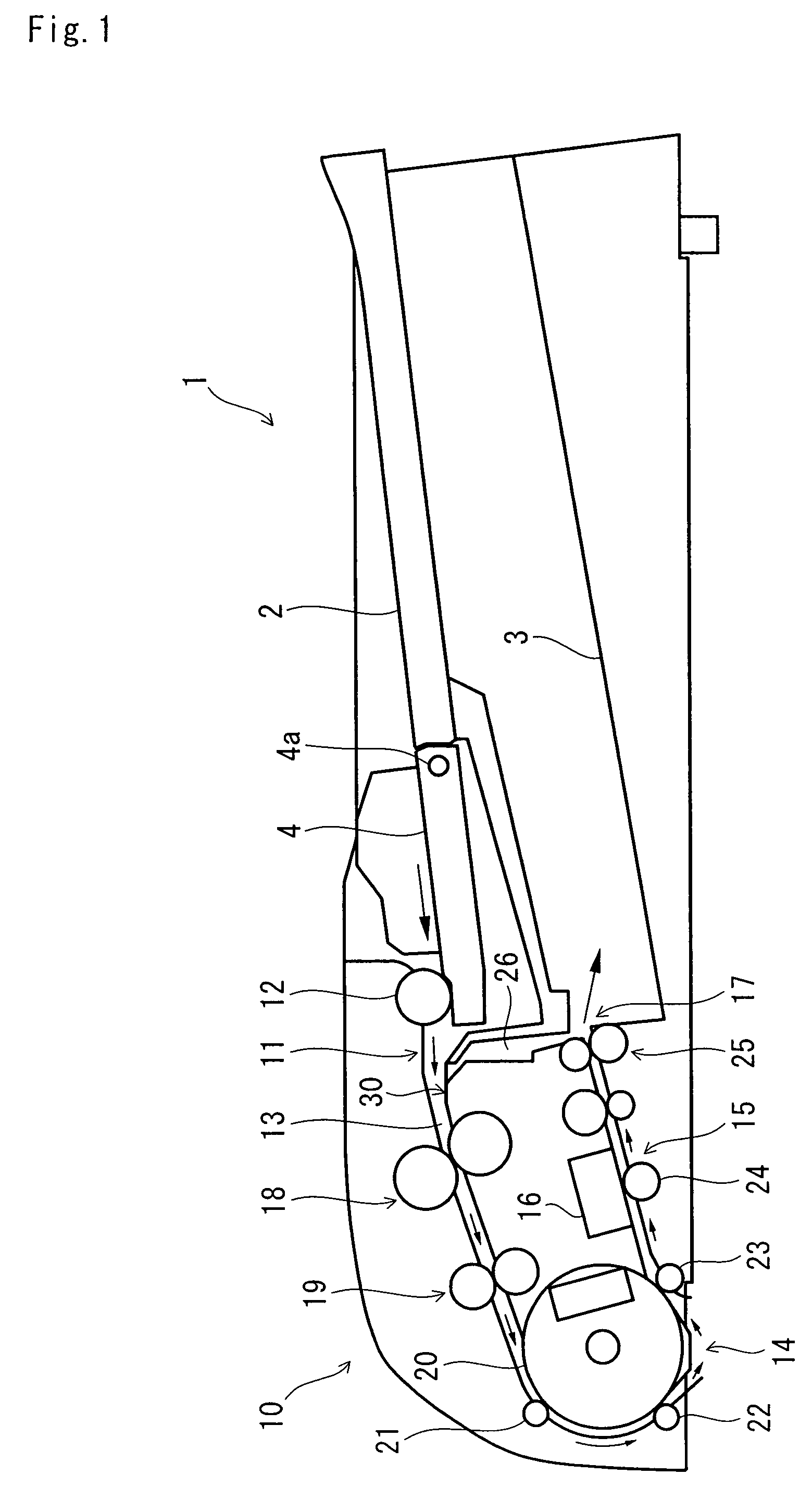
[0042]First, an outline description will be given of the construction of a document conveying apparatus of a first embodiment according to the invention with reference to FIG. 1. FIG. 1 is a schematic vertical cross-sectional front view of the document conveying apparatus. Solid line arrows in FIG. 1 represent the passage and the direction through and in which a document sheet is conveyed. It is assumed that the herein-described document conveying apparatuses embodying the invention are designed as those to be mounted in an upper portion of an image forming apparatus such as a copier or a facsimile machine, or of a multifunctional device having copying, facsimile and other capabilities.

[0043]As shown in FIG. 1, the document conveying apparatus 1 is provided with a document stacking tray 2, a document feeding section 10 and a document ejection tray 3.

[0044]The document stacking tray 2 is arranged in an upper portion of the document conveying apparatus 1. Document sheets can be placed...

second embodiment

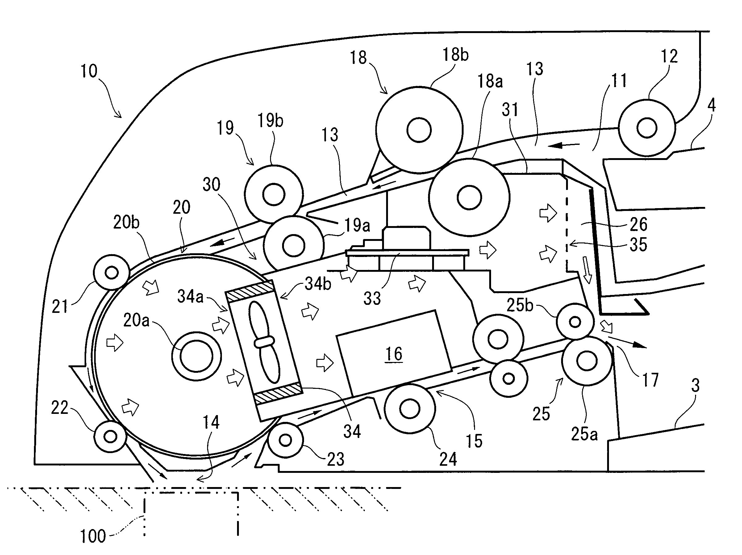
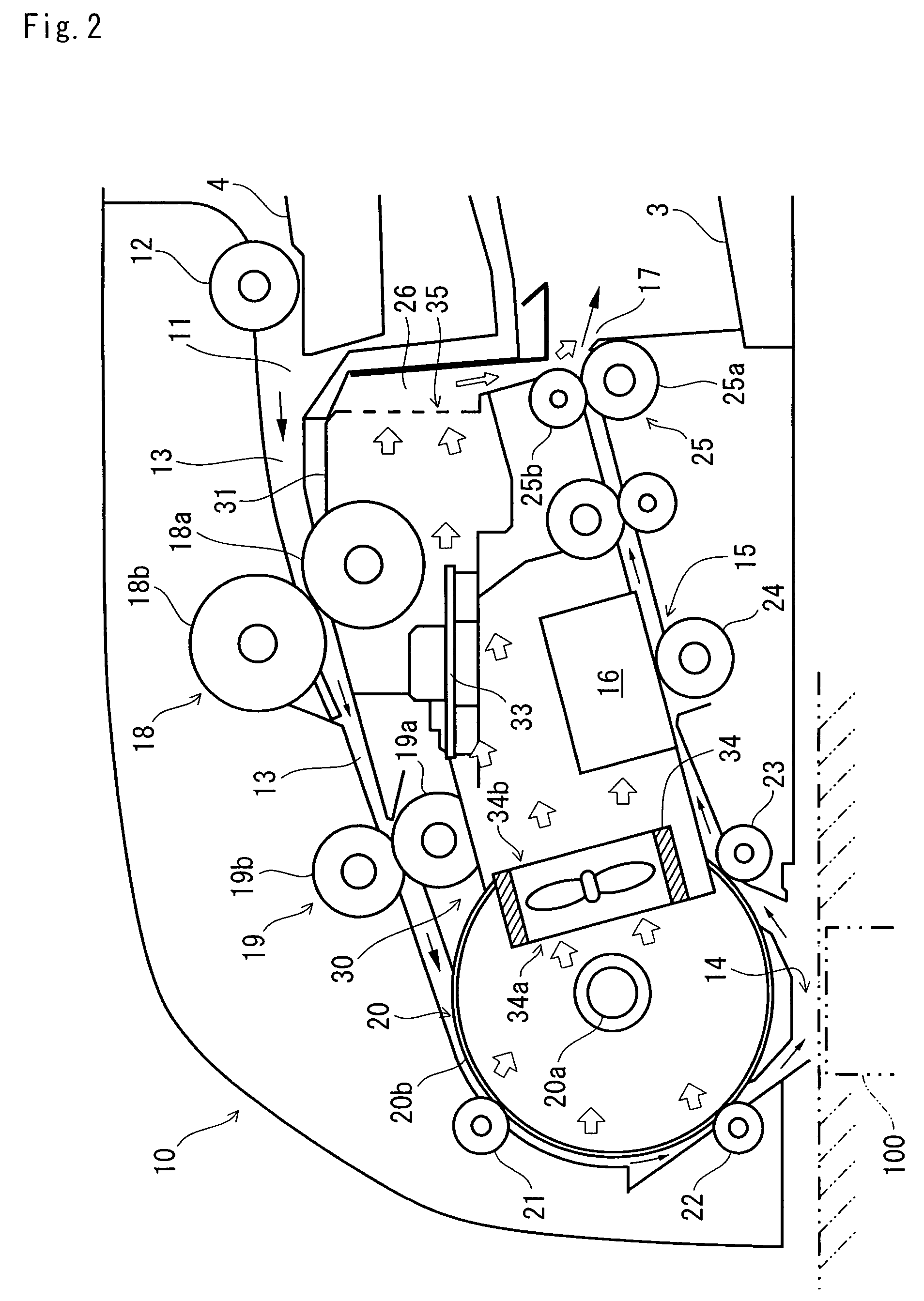
[0075]Next, a detailed description will be given of the construction of a document conveying apparatus of a second embodiment according to the present invention with reference to FIGS. 6 to 8. FIG. 6 is a vertical cross-sectional enlarged front view of a portion around an exhaust louver in the document conveying apparatus. FIG. 7 is a perspective view of the document conveying apparatus shown in FIG. 6 as seen from the direction of the document stacking tray. FIG. 8 is a perspective view, as seen from the direction of the document stacking tray, of the document conveying apparatus in a state where the document stacking tray is removed. In FIG. 6, solid line arrows represent the passage and the direction through and in which the document sheet is conveyed; outline arrows represent the path and the direction along and in which air is passed.

[0076]The basic construction of this embodiment is the same as that of the first embodiment described with reference to FIGS. 1 to 5, and accordin...


PUM

PropertyMeasurementUnit
widthaaaaaaaaaa
electric poweraaaaaaaaaa
temperatureaaaaaaaaaa

Abstract

A document conveying apparatus (1) includes a conveying unit (30) inside a document feeding section (10), and the conveying unit (30) includes two fans (34) for cooling the inside of the document conveying apparatus (1). The fans (34) are arranged to pass air from upstream to downstream with respect to the document conveying direction. Thus, the stream of air produced by the fan (34) flows along the document conveying direction so that a document sheet is conveyed without being affected by a braking effect. Moreover, the air stream produced by the fan (34) flows along the document conveying passage (13) both on the air intake side and the air exhaust side of the fan (34). This facilitates the conveying of a document sheet by pulling it on the air intake side of the fan (34) and pushing it on the air exhaust side of the fan (34).

Description

[0001]This application is based on Japanese Patent Application No. 2006-070548 filed on Mar. 15, 2006 and Japanese Patent Application No. 2006-199053 filed on Jul. 21, 2006, the contents of both of which are hereby incorporated by reference.BACKGROUND OF THE INVENTION[0002]1. Field of the Invention[0003]The present invention relates to a document conveying apparatus that can be applied to image forming apparatuses such as copiers and facsimile machines.[0004]2. Description of Related Art[0005]Some image forming apparatuses, such as copiers and facsimile machines, are provided with a document conveying apparatus that automatically feeds a plurality of document sheets to a document reading section. The document conveying apparatus separates and conveys one document sheet after another from the topmost layer of a stack of document sheets stacked on a document stacking tray. The image data on the surface of the document sheets is read by the document reading section, and then the docume...

Claims


Application Information

Patent Timeline
Patent Type & Authority Patents(United States)
IPC IPC(8): B65H3/14G03G21/20
CPCB65H5/00B65H15/00H04N1/00981B65H2301/333B65H2301/4461B65H2406/11
Inventor KAWASHIMA, SHINSUKEYOSHIUCHI, KATSUHIRO
Owner KYOCERA DOCUMENT SOLUTIONS INC
Why Eureka
Try Eureka