Heat pipe

A heat pipe and pipe body technology, applied in the field of heat pipes, can solve the problems of liquid transport capacity drop, disintegration, thermal resistance increase, etc., and achieve the effect of increasing fluid transport capacity and enhancing heat transfer performance

Inactive Publication Date: 2007-05-02
FU ZHUN PRECISION IND SHENZHEN +1
View PDF0 Cites 18 Cited by
  • Summary
  • Abstract
  • Description
  • Claims
  • Application Information

AI Technical Summary

Problems solved by technology

However, when the heat pipe is flattened, the capillary structure is prone to deformation and disintegration, which greatly reduces its liquid delivery capacity, resulting in a significant decrease in the maximum heat transfer of the heat pipe and an increase in thermal resistance.

Method used


Image

  • Heat pipe
  • Heat pipe
  • Heat pipe

Examples


Embodiment Construction

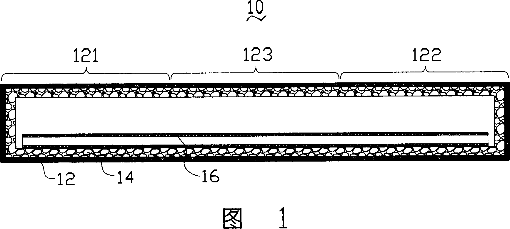
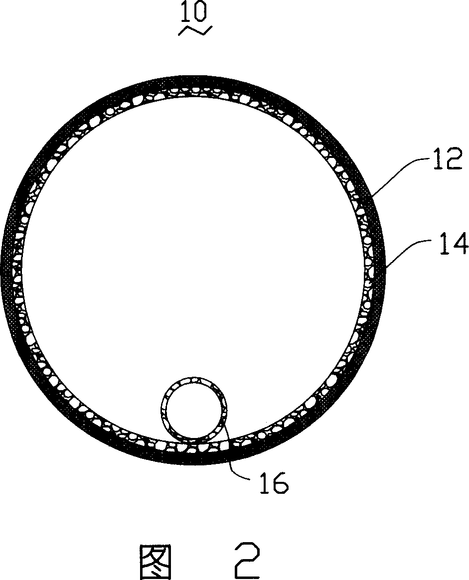
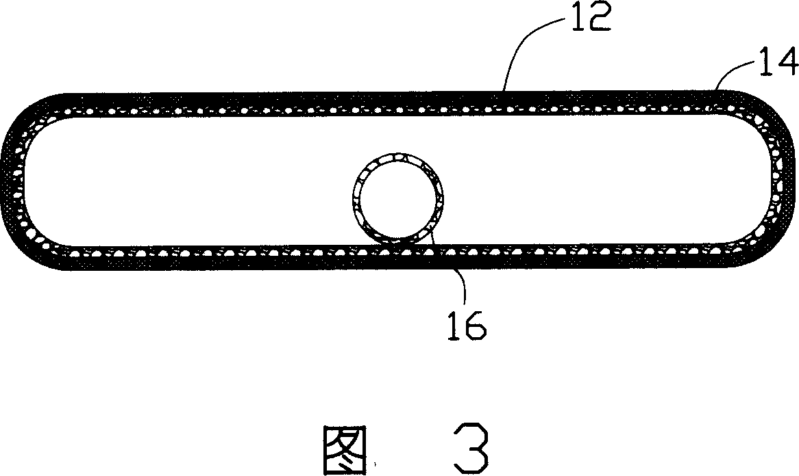
[0016] Please refer to FIG. 1 , the heat pipe 10 includes a tube body 12 , a main capillary structure 14 , an auxiliary capillary structure 16 and a working medium.

[0017] The tube body 12 is made of a material with good thermal conductivity such as copper, which can transfer the heat generated by a heating element to the inside of the tube body 12. The heat insulating part 123 of the evaporating part 121 and the condensing part 122 .

[0018] The working medium is filled in the tube body 12 and is water, wax, alcohol, methanol and other substances with a relatively low boiling point. The working medium absorbs heat and evaporates from the evaporation part 121 of the pipe body 12, moves to the condensation part 122 with heat, condenses into a liquid after releasing heat in the condensation part 122, releases the heat, and completes heat dissipation to the heating element.

[0019] The capillary structure 14 is arranged on the inner wall of the tube body 12, and can be in th...


PUM


Abstract

A heat conduction tube is prepared as setting tube to be longitudinal unit, setting master capillary structure on internal wall of tube and packing work media in tube, setting at least one auxiliary capillary structure (ACS) in tube, making ACS be longitudinal unit and extending it between heat absorption and heat discharge units of tube unit then fitting it with master capillary structure, setting cross section size of ACS to be less than internal hole size of tube.

Description

【Technical field】 [0001] The invention relates to a heat pipe, in particular to a heat pipe with good heat transfer performance. 【Background technique】 [0002] At present, heat pipes have been widely used in electronic components with large heat generation due to their advantages of high heat transfer. [0003] When the heat pipe is working, the low-boiling-point working medium filled in the pipe body absorbs the heat generated by the heating electronic components in the evaporation part, evaporates and vaporizes, moves to the condensation part with heat, and releases the heat by liquefaction and condensation in the condensation part. Dissipate heat from electronic components. The vaporized working medium flows back to the evaporation part under the action of the capillary structure of the wall of the heat pipe, and continues to evaporate, vaporize, liquefy and condense, so that the working medium circulates inside the heat pipe and continuously emits the heat generated by...

Claims


Application Information

Patent Timeline
Patent Type & Authority Applications(China)
IPC IPC(8): F28D15/04
CPCF28D15/0233F28D15/046G06F1/20
Inventor 张长生刘睿凯萧凯峰王肇浩
Owner FU ZHUN PRECISION IND SHENZHEN
Why Eureka
Try Eureka