
Edge lit sign with illuminated image

a technology of illuminated signs and edges, applied in the direction of illuminated signs, display means, instruments, etc., can solve the problems of precision in mounting, and achieve the effect of uniform illumination of geometric designs

Inactive Publication Date: 2010-03-23
IMAGEWORKS DISPLAY & MARKETING GROUP
View PDF35 Cites 43 Cited by
  • Summary
  • Abstract
  • Description
  • Claims
  • Application Information

AI Technical Summary

Benefits of technology

[0012]In this illuminated sign, adjacent light emitting diodes are spaced apart between opposite ends of the linear light source array. The geometric design formed on the flat panel has a length, parallel to the linear array, greater than the spacing between adjacent light emitting diodes. The multiple light emitting diodes illuminate the geometric design, which forms a discontinuity on one surface of the flat panel, to redirect light engaging indented surfaces forming the geometric design. The diffusion surface on the edge of the flat panel is juxtaposed to the linear array so that the diffusion surface laterally disperses light emitted by the light emitting diodes adjacent the one edge of the flat panel to more evenly illuminate the geometric design.

Problems solved by technology

These devices, however, use a separate diffuser and light transmissive panel and appear to require precision in mounting the LED's relative to either the diffuser or the clear panel.

Method used


Image

  • Edge lit sign with illuminated image
  • Edge lit sign with illuminated image
  • Edge lit sign with illuminated image

Examples


Embodiment Construction

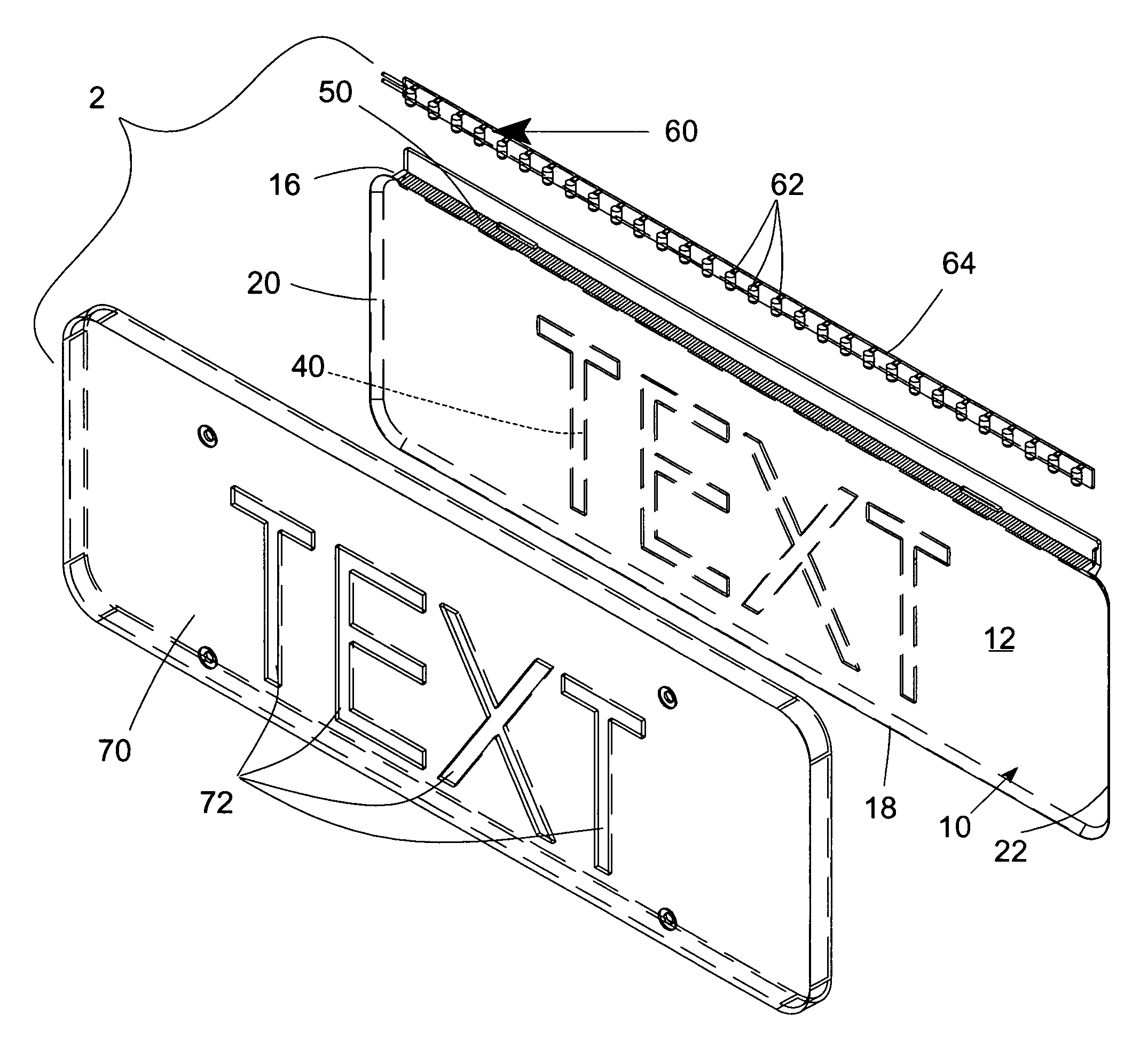
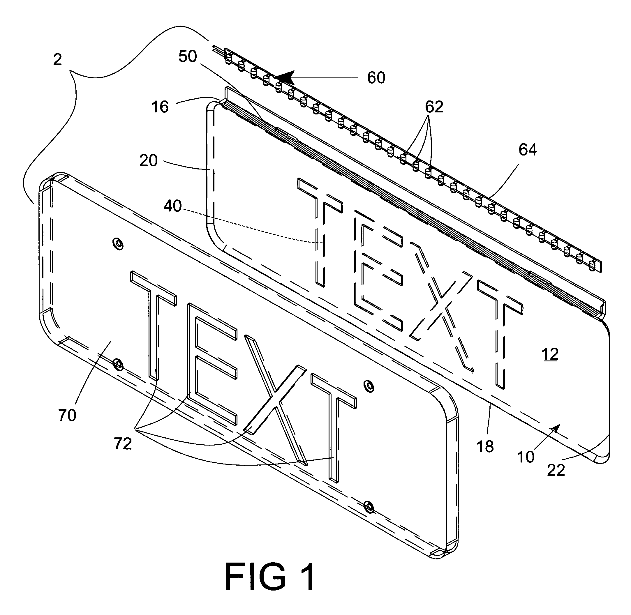
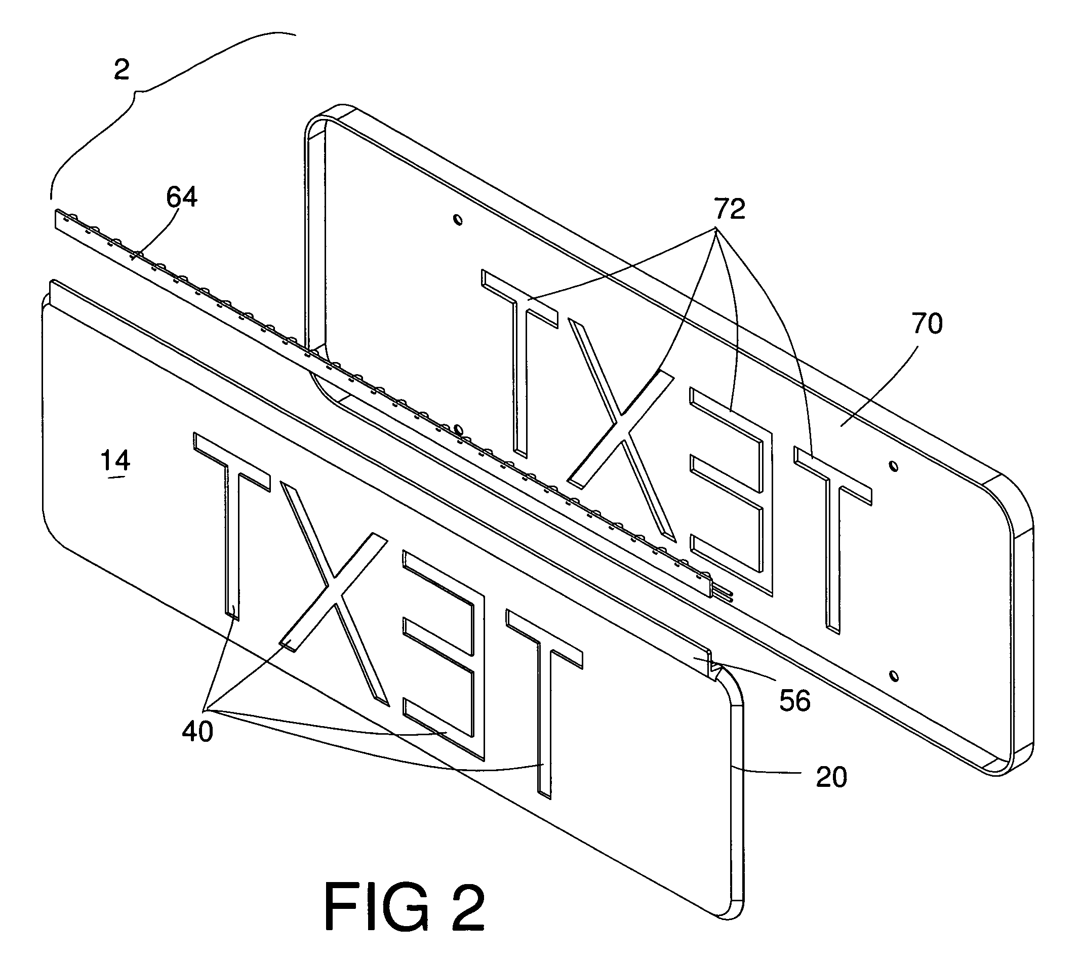
[0033]The preferred embodiment of the edge lit illuminated sign 2 according to this invention includes a one-piece panel 10 with a geometric figure 40 and a light diffusion surface 50, both formed on the one-piece panel. A linear array 60 of spaced discrete light sources, such as light emitting diodes 62, is mounted along one illuminated edge 16 of the panel 10. The geometric figure 40 is depicted here as representative text, but it should be understood that the figure 40 is not limited to textural material, and is especially suited to represent artwork, such as advertising logos or trademarks. In the preferred embodiment, this one-piece panel 10 is molded from a light transmissive or transparent material, such as an acrylic. In the preferred embodiment, the geometric figure 40 and the light diffusion surface 50 are both formed as molded features when the panel 40 is injection molded. It should be understood, however, that in other embodiments, either or both the geometric figure 40...


PUM


Abstract

A sign is edge lit and illuminated by an array of light emitting diodes disposed along an edge of a light transmissive panel. A light diffusion surface, which can be formed by a series of serrations on the panel edge, disperses light from the discrete light emitting diodes in the array. A geometric figure, which can be text or graphics or both is formed on one face of the panel by grooves, which redirect diffused light so that an illuminated image, corresponding to the geometric figure, can be seen on the front of the panel. The grooves forming the figure and the light diffusion surface comprise parts of a one-piece panel, and the grooves and the light diffusion surface can be formed when the panel is injection molded.

Description

BACKGROUND OF THE INVENTION[0001]1. Field of the Invention[0002]This invention relates to signs illuminated by edge lighting. This invention also relates to the use of discrete light sources, such as light emitting diodes to illuminate a figure, so that only the figure is illuminated relative to the substrate on which the figure is formed.[0003]2. Description of the Prior Art[0004]Edge lit signs or signboards employing fluorescent lamps mounted adjacent one edge of a light transmissive panel have been employed to illuminate characters or figures on one face of the panel. Since a standard tubular fluorescent lamp emits a substantially uniform illumination along its entire length, it will uniformly illuminate a figure or a series of characters extending between opposite ends of the fluorescent lamp and presumably along substantially the entire length of the sign.[0005]It has been recognized that light emitting diodes possess certain advantages over fluorescent lamps when used in edge ...

Claims


Application Information

Patent Timeline
IPC IPC(8): G09F13/18
CPCG02B6/0016G09F13/18G02B6/0035G02B6/006G02B6/0068G02B6/0083
Inventor WELKER, BRIAN HARTISAACS, GREGORY SCOTT
Owner IMAGEWORKS DISPLAY & MARKETING GROUP
Learn More