Multiple resistance curves used to vary resistance in exercise apparatus

a technology of resistance curves and exercise equipment, which is applied in the direction of sport equipment, muscle exercise devices, weights, etc., can solve the problems of not providing a selectable resistance pattern, no commercially viable means of producing an exercise machine, and the tendency to use poor form or throw the whole body into an exercise movemen

Inactive Publication Date: 2010-03-23
HULLS CHRISTOPHER R
View PDF7 Cites 12 Cited by
  • Summary
  • Abstract
  • Description
  • Claims
  • Application Information

AI Technical Summary

Problems solved by technology

There are currently no commercially viable means of producing an exercise machine that offers different resistance patterns.
For those new to exercise equipment, there is a tendency to use poor form or to throw the entire body into an exercise movement.
The related are does not provide a selectable resistance pattern to offset the momentum problem.
The related art has made a few attempts to deliver a method of changing resistance patterns within an exercise machine, but all are prohibitively expensive or too cumbersome to achieve commercial success.
Both of these methods, however, prove insufficient due to the limited variability of the resistance.
Furthermore, the ability to increase and then decrease the resistance experienced along the range of motion was also limited.
Again, the amount and range of variability was limited.
a) Without changing the shaped cam, the user is limited to a single pattern of resistance.
b) Changing of the cam is a time consuming and potentially dangerous process. Even with the multiple cams on a drum design, the load must be taken off of the cam roller, and a user's fingers could easily be caught between the two parts.
c) There are more moving parts than necessary to require the desired effect.
d) The design still relies on the traditional shaped cam method to vary the resistance pattern.
e) The result is unaesthetic.
f) The proper use of the disclosed system is counterintuitive.
Utilizing a computer controller, the desired effect is achieved quite well, but the costs are prohibitive, and the interface is overly complex for a casual user.

Method used


Image

  • Multiple resistance curves used to vary resistance in exercise apparatus
  • Multiple resistance curves used to vary resistance in exercise apparatus

Examples


Embodiment Construction

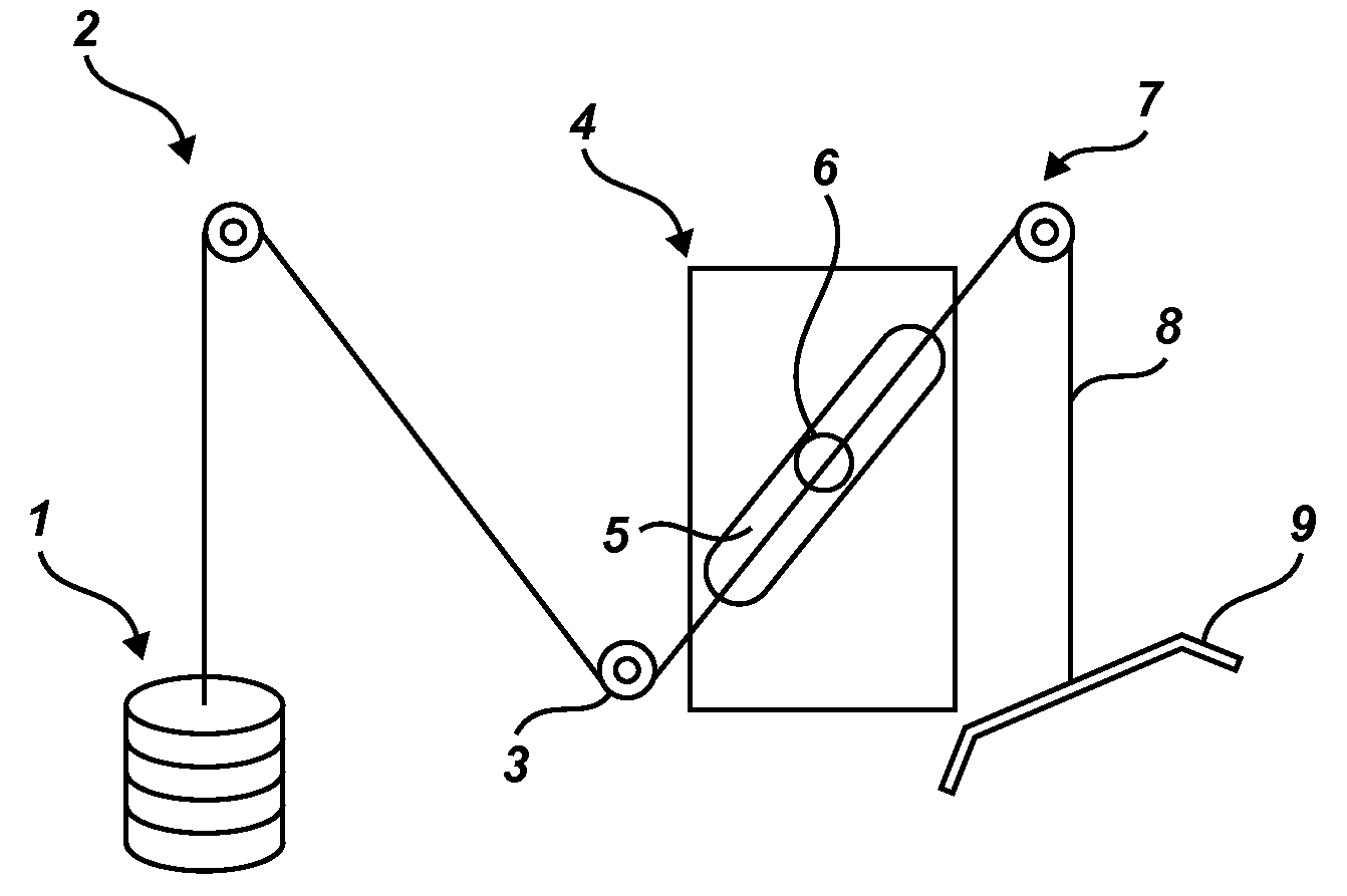
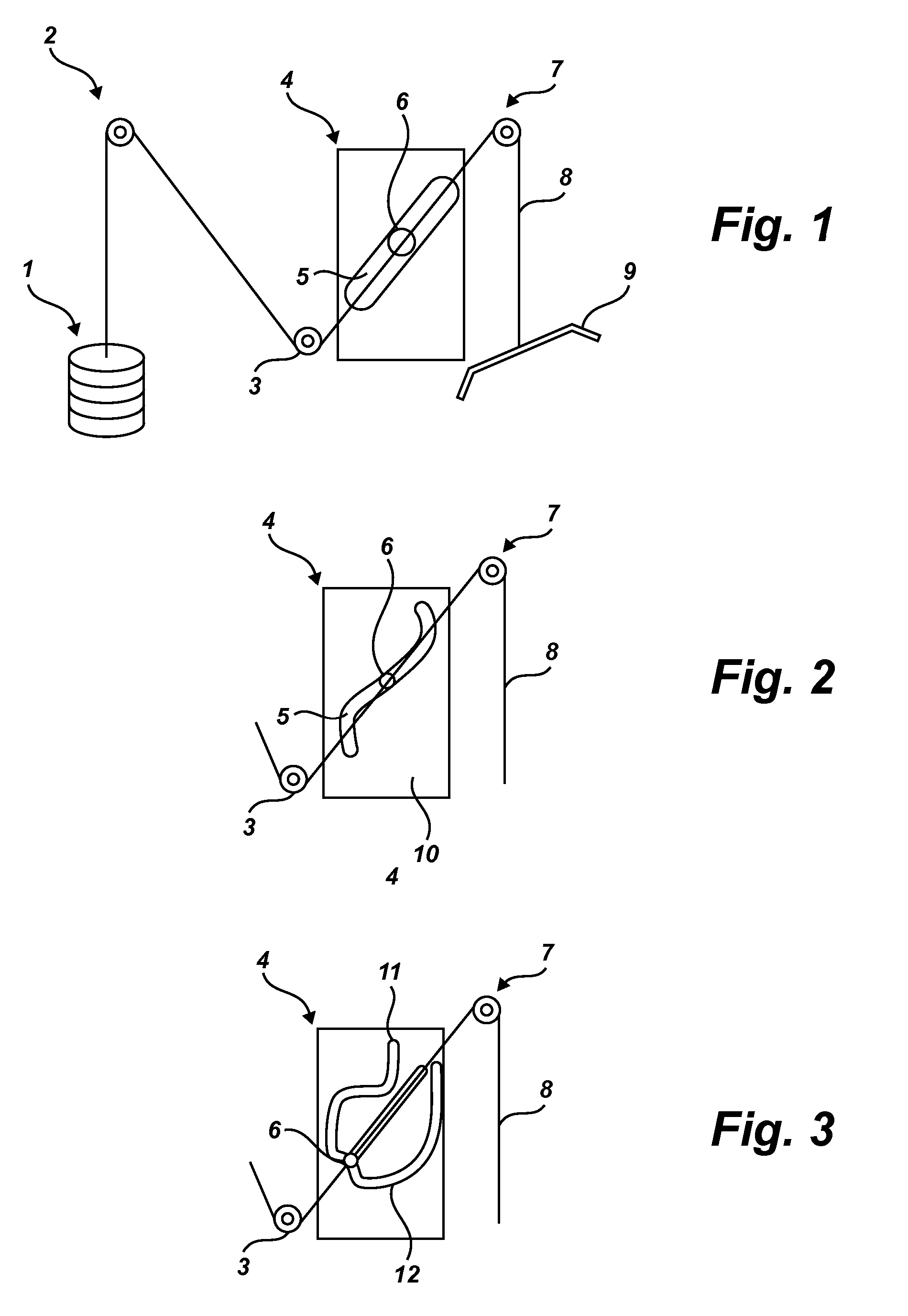
[0027]Exercise movements and weight selection are similar to other traditional exercise machines. For purposes of illustration, a pull-down machine is illustrated, but the principles of the invention are equally applicable to seated sit-up machines, standing curl machines, seated curl machines, leg press machines, pushdown bars and all other weight resistance apparatuses. However, unlike the related art, the user is allowed to conveniently select a resistance curve or resistance track.

[0028]To select the appropriate resistance curve, the user slides the roller along the track via a handle to the starting location of the desired curve. The resistance encountered to select a different starting location is minimal, as the track is designed so that the roller moves towards the pivot point when selecting a curve, thereby the only the weight of the actuating device must be overcome. This allows the resistance curve or resistance track to be changed without removing or changing the weight ...


PUM


Abstract

Changing resistance patterns in an exercise machine is accomplished by moving a cable pivot point within a channel. The channel may take the form of numerous shapes. Multiple shapes may comprise one continuous channel. The placement of the pivot point and surrounding channel shape dictate the resistance pattern along the range of exercise motion. The pivot point is attached to two cables, one leading to a weight, the other leading to the user of the exercise machine.

Description

CROSS-REFERENCE TO RELATED APPLICATIONS[0001]This application claims the benefit of U.S. provisional application 60 / 759,642 filed on Jan. 17, 2006 and titled “Dynamically variable resistance exercise apparatus” which is incorporated herein by reference.STATEMENT REGARDING FEDERALLY SPONSORED RESEARCH OR DEVELOPMENT[0002]Not ApplicableREFERENCE TO A SEQUENCE LISTING[0003]Not ApplicableBACKGROUND OF THE INVENTION[0004](1) Field of the Invention[0005]The invention relates to means and methods of creating and using exercise machines that provide dynamic and variable resistance throughout the range of an exercise motion. A machine may be fitted with a plurality of different shaped curved members or channels that vary resistance along a range of motion.[0006](2) Description of the Related Art[0007]Many exercise machines are known in the related art and attempt to provide either uniform or changing resistance along a range of motion. For example, in a traditional pulley system, uniform for...

Claims


Application Information

Patent Timeline
Patent Type & Authority Patents(United States)
IPC IPC(8): A63B21/062A63B21/00
CPCA63B21/062A63B21/154A63B21/0628
Inventor HULLS, CHRISTOPHER R.
Owner HULLS CHRISTOPHER R
Why Eureka
Try Eureka