Hybrid primary optical component for optical concentrators

a technology of optical concentrators and primary optical components, applied in the field of optical concentrator configurations, can solve the problems of large, high-quality fresnel lenses as conventionally used, prohibitively expensive medium-scale applications such as commercial rooftop systems, and the loss of optical concentrators, etc., and achieve the effect of not being suitable by itself for certain articulating concentrators

Inactive Publication Date: 2010-03-30
SUNCORE PHOTOVOLTAICS
View PDF157 Cites 20 Cited by
  • Summary
  • Abstract
  • Description
  • Claims
  • Application Information

AI Technical Summary

Benefits of technology

[0016]The present invention provides numerous solutions helpful singly or in combination to overcome and / or alleviate one or more of the problems present in prior art concentrators through the use of a hybrid reflective / refractive optical component. In preferred embodiments, the present invention provides a light collecting and concentrating optical component that includes both refractive and reflective elements. The component is hybrid in the sense that each element handles light collection and focusing for different portions of an aperture of the optical component. At least a portion of the aperture uses a refractive element while another portion of the primary aperture uses a reflective element. Either the reflective and / or referactive elements can be imaging and / or nonimaging. Advantageously, this allows many benefits of both refractive and reflective elements to be realized while avoiding conventional drawbacks.
[0018]In particularly preferred embodiments of this invention, the refractive element of the hybrid optical component is included in a transparent cover that fits over the light receiving end of the reflective element. Such an arrangement offers the significant advantage that the complete concentration system may be protectively enclosed beneath the protective cover and within the walls of the reflector (e.g., reflective trough or dish).

Problems solved by technology

Large, high quality Fresnel lenses as conventionally used, however, can be prohibitively expensive for medium scale applications such as commercial rooftop systems.
In addition, surface discontinuities present on Fresnel lenses tend to make them lossy (i.e., inasmuch as some of the light that is desirably focused may instead be absorbed and / or directed away from the focus) compared to standard lenses or reflective solutions.
Another disadvantage of the Fresnel concentrator as conventionally used is that it is not suitable by itself for certain articulating concentrators that require self-powering.
Unfortunately, a conventional Fresnel concentrator provides negligible paths for diffuse radiation to strike a solar cell located at the focus of the lens and therefore is usually unable to generate sufficient power to articulate itself when not aligned with the sun.
However, because high concentration ratios tend to require a CPC with a large height / width ratio, the packing density for multiple articulating concentrators including CPC's can be limited.
This relatively high height / width ratio factor makes conventional CPC's, by themselves, poorly suited for multiple articulating concentrator systems such as those described in Assignee's U.S. Provisional Patent Application No. 60 / 691,319, filed Jun. 16, 2005, in the names of Hines et al., titled PLANAR CONCENTRATING PHOTOVOLTAIC SOLAR PANEL WITH INDIVIDUALLY ARTICULATING CONCENTRATOR ELEMENTS and Assignee's U.S. Provisional Patent Application No. 60 / 759,778, filed Jan. 17, 2006, in the name of Hines, titled CONCENTRATING SOLAR PANEL AND RELATED SYSTEMS AND METHODS, which applications are incorporated herein by reference in their respective entireties for all purposes,.
As another drawback, parabolic troughs and dishes have aperture regions that are, in practice, unusable for concentrating.
Portions of the apertures of these optical elements are unusable because both the bottom and inverted focusing configurations can be affected by angle of incidence limits at the target focal plane.
Inverted focus reflectors suffer from a similar effect except that the aperture penalty occurs near the periphery of the reflector.
In addition, as is typical of inverted focus configurations, reflector 50 suffers from self-shadowing such that rays nearest to the optical axis in region 64 are blocked by the target at the focal plane 48 itself, further reducing the light-collecting efficiency of the system.
Conventional optical designs can present challenges for photovoltaic devices that would like to use self-powered articulation to aim light concentrating components at the source of incident light, e.g., the sun.
However, as implemented conventionally, this design choice occurs at the expense of the aforementioned limitations of the bottom focus reflector.
Devices that instead use inverted focus reflectors, on the other hand, generally provide only very limited optical paths for diffuse radiation to reach the target, as the target, e.g., a solar cell, is facing away from diffuse radiative sources.
Also, the reflected field of view in the primary mirror tends to be very narrow.
These conventional bottom focus and inverted focus reflectors are therefore not well-suited to self-powered systems.
However, these generally include multiple, precision aligned surfaces that may be cost-prohibitive for medium-scale applications.
Additionally, in the case of a long parallel slat form, additional support structure may be required that would tend to create undesirable optical obscurations.
Further, in a manner that is analogous to the limitations of a refractive Fresnel lens discussed above, such a design has a limited ability to collect and focus diffuse light to provide for self-powering.
The significant disadvantage of these approaches is that they incur the expense and optical losses of two separate, full-aperture optical elements.

Method used


Image

  • Hybrid primary optical component for optical concentrators
  • Hybrid primary optical component for optical concentrators
  • Hybrid primary optical component for optical concentrators

Examples


Embodiment Construction

[0031]The embodiments of the present invention described below are not intended to be exhaustive or to limit the invention to the precise forms disclosed in the following detailed description. Rather a purpose of the embodiments chosen and described is so that the appreciation and understanding by others skilled in the art of the principles and practices of the present invention can be facilitated.

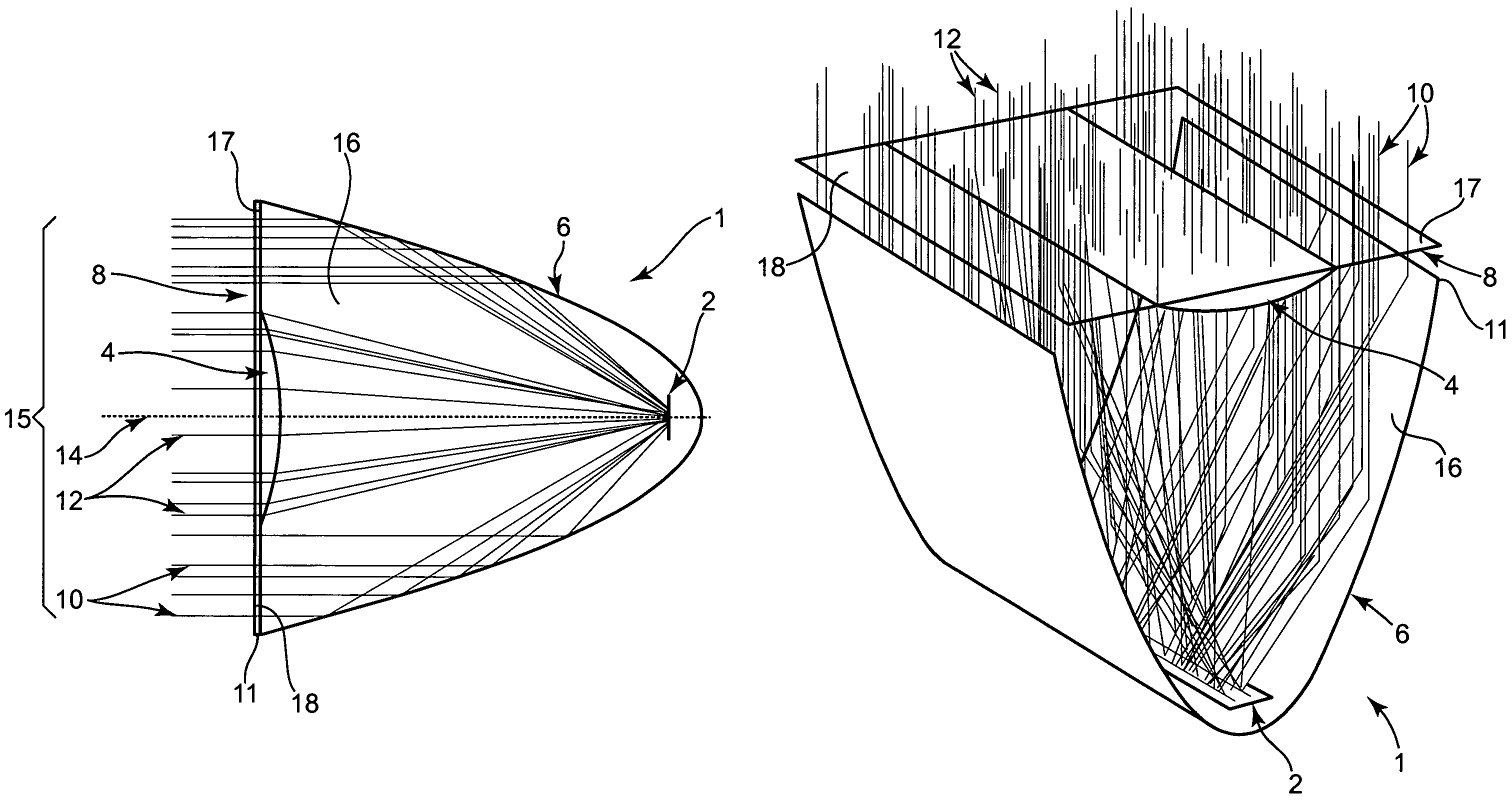
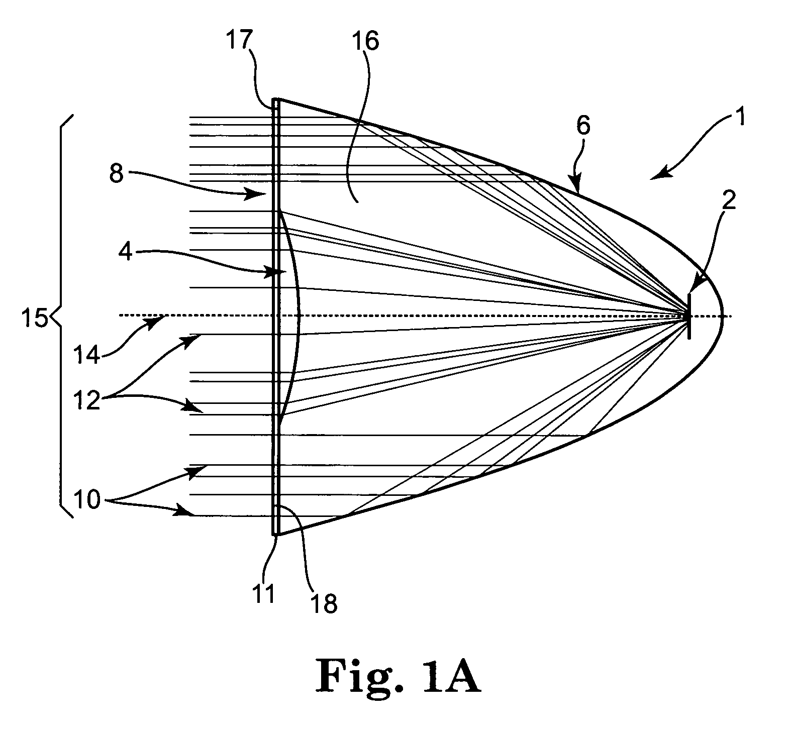
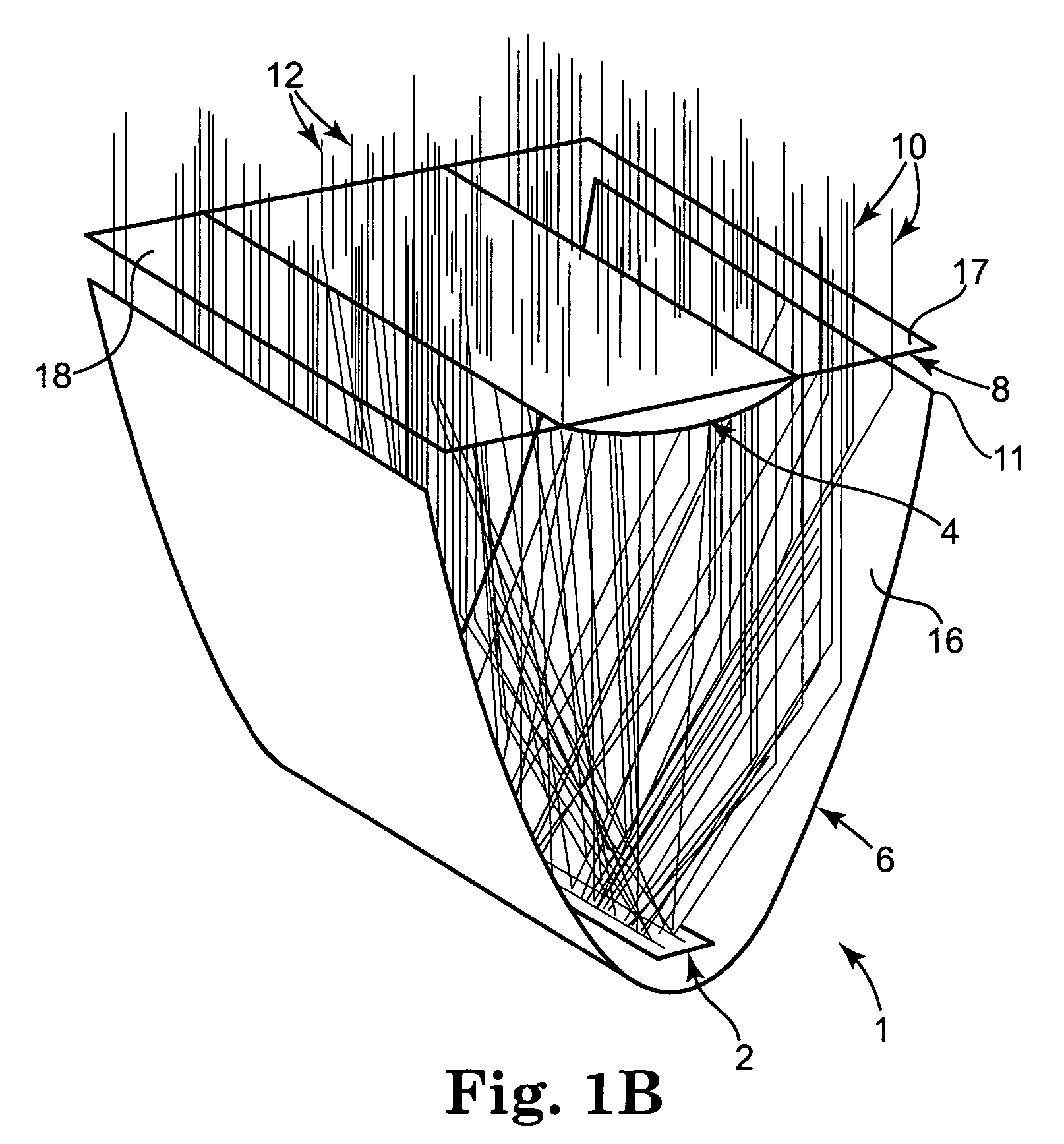
[0032]FIGS. 1a, 1b, and 7 show one preferred embodiment of a hybrid primary optical component 1 of this invention. For purposes of illustration optical component 1 is in the form of a line concentrator. The full aperture 15 of component 1 spans the width (in the case of a line concentrator) or diameter (in the case of a point concentrator) of the light receiving end 11 of a reflective element in the form of a bottom focusing dish 6. The hybrid primary optical component 1 includes a cover 8 fitted onto light receiving end 11. Together, the cover 8 and dish 6 provide a protective housing for...


PUM


Abstract

A hybrid optical component that collects and concentrates incident light. The hybrid component includes both refractive and reflective elements. In preferred embodiments, refractive and reflective components focus rays on a common focal plane generally located at the bottom of the reflector where they are absorbed by a device such as a photovoltaic (solar) cell. Additionally, the optical component combines both imaging and non-imaging optical elements into a single device, for improved overall performance.

Description

PRIORITY CLAIM[0001]The present non-provisional patent Application claims priority under 35 USC §119(e) from U.S. Provisional Patent Application having Ser. No. 60 / 759,909, filed on Jan. 17, 2006, by Hines et al., and titled A HYBRID PRIMARY OPTICAL COMPONENT FOR OPTICAL CONCENTRATORS, wherein the entirety of said provisional patent application is incorporated herein by reference.FIELD OF THE INVENTION[0002]This invention relates to optical configurations applied to optical concentrating systems, such as line or point solar collectors that receive and concentrate incident light towards target(s). The target(s) may be device(s) such as photovoltaic (solar) cell(s).BACKGROUND OF THE INVENTION[0003]Optical concentrating systems, such as solar collectors, concentrate light toward a focus of the optical system. In general, there are two categories of concentrators. Line concentrators concentrate incident light in one dimension so that the focus is a line. Point concentrators concentrate ...

Claims


Application Information

Patent Timeline
Patent Type & Authority Patents(United States)
IPC IPC(8): G02B17/00F24S23/30F24S23/70F24S23/71F24S23/74
CPCF24J2/06F24J2/08F24J2/12F24J2/14G02B3/08H01L31/0547G02B19/0042G02B19/0028H01L31/0543F24J2/085Y02E10/44Y02E10/45Y02E10/52Y02E10/42F24S23/00F24S23/30F24S23/31F24S23/71F24S23/74G02B5/10H02S40/22Y02E10/40
Inventor HINES, BRADEN E.JOHNSON, JR., RICHARD L.
Owner SUNCORE PHOTOVOLTAICS
Why Eureka
Try Eureka