Robust sensor fusion for mapping and localization in a simultaneous localization and mapping (SLAM) system

a sensor and localization technology, applied in the field of combining or combining data, can solve the problems of not updating the estimate of characteristic correctly, not convergently, and not knowing the estimate of characteristic,

Active Publication Date: 2010-03-30
IROBOT CORP
View PDF59 Cites 188 Cited by
  • Summary
  • Abstract
  • Description
  • Claims
  • Application Information

AI Technical Summary

Problems solved by technology

The problem of estimating a characteristic that cannot be known with certainty is common.
However, a disadvantage of the standard particle filter is that it often fails to update the estimate of characteristic correctly, and, often, if the error in the initial estimate is large, the estimate converges relatively slowly, or not at all.
This weakness is due to the limited number of samples used to approximate the relevant probability distributions; namely, the samples tend to cluster more than is appropriate in regions where the density function is relatively large.
A conventional technique to reduce this limitation is to use a relatively large number of samples (particles), which disadvantageously results in a large computational requirement on the filtering process.
In addition, the statistical properties of the measurements are typically not known with accuracy, which can cause the performance of particle filter to break down.
However, immediately after the kidnapping, this estimate is very likely to be wrong because that most conventional methods of data fusion are not able to recover the pose in a short amount of time.
An important weakness of the methods described in Montemerlo, et al., id. is that if the robot is kidnapped a relatively short time before the map is expanded (i.e., a new feature, such as a new landmark, is added to the map), then it will be relatively difficult for the robot to recover and fully correct the map.
A second disadvantage of the methods described in reference 4 lies in the so-called “landmarks” that form the basis for its map.
While relatively accurate over relatively short distances, dead reckoning sensing is prone to drift over time.
Disadvantageously, drift errors can accumulate in dead reckoning measurements.

Method used


Image

  • Robust sensor fusion for mapping and localization in a simultaneous localization and mapping (SLAM) system
  • Robust sensor fusion for mapping and localization in a simultaneous localization and mapping (SLAM) system
  • Robust sensor fusion for mapping and localization in a simultaneous localization and mapping (SLAM) system

Examples


example 1

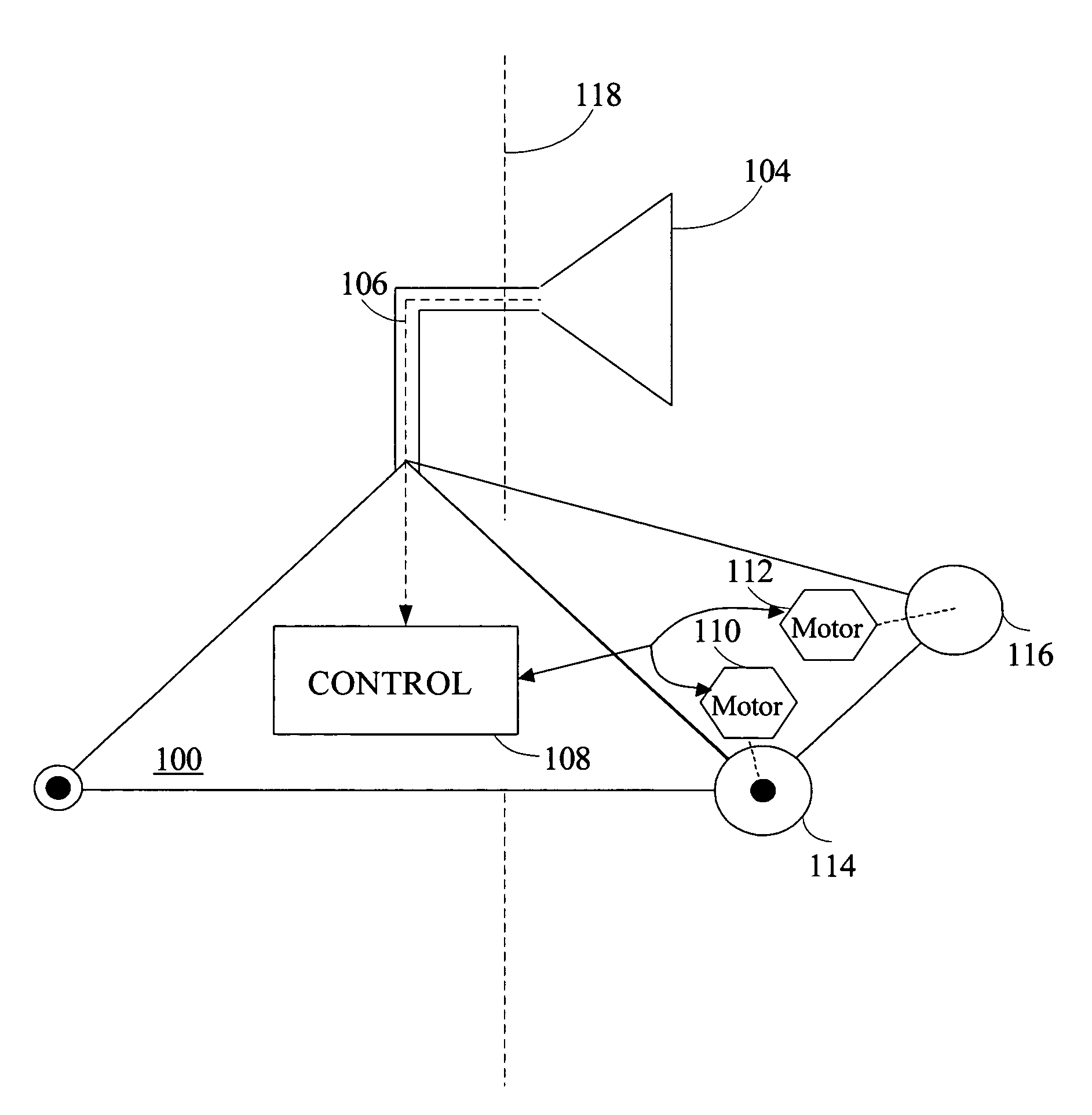
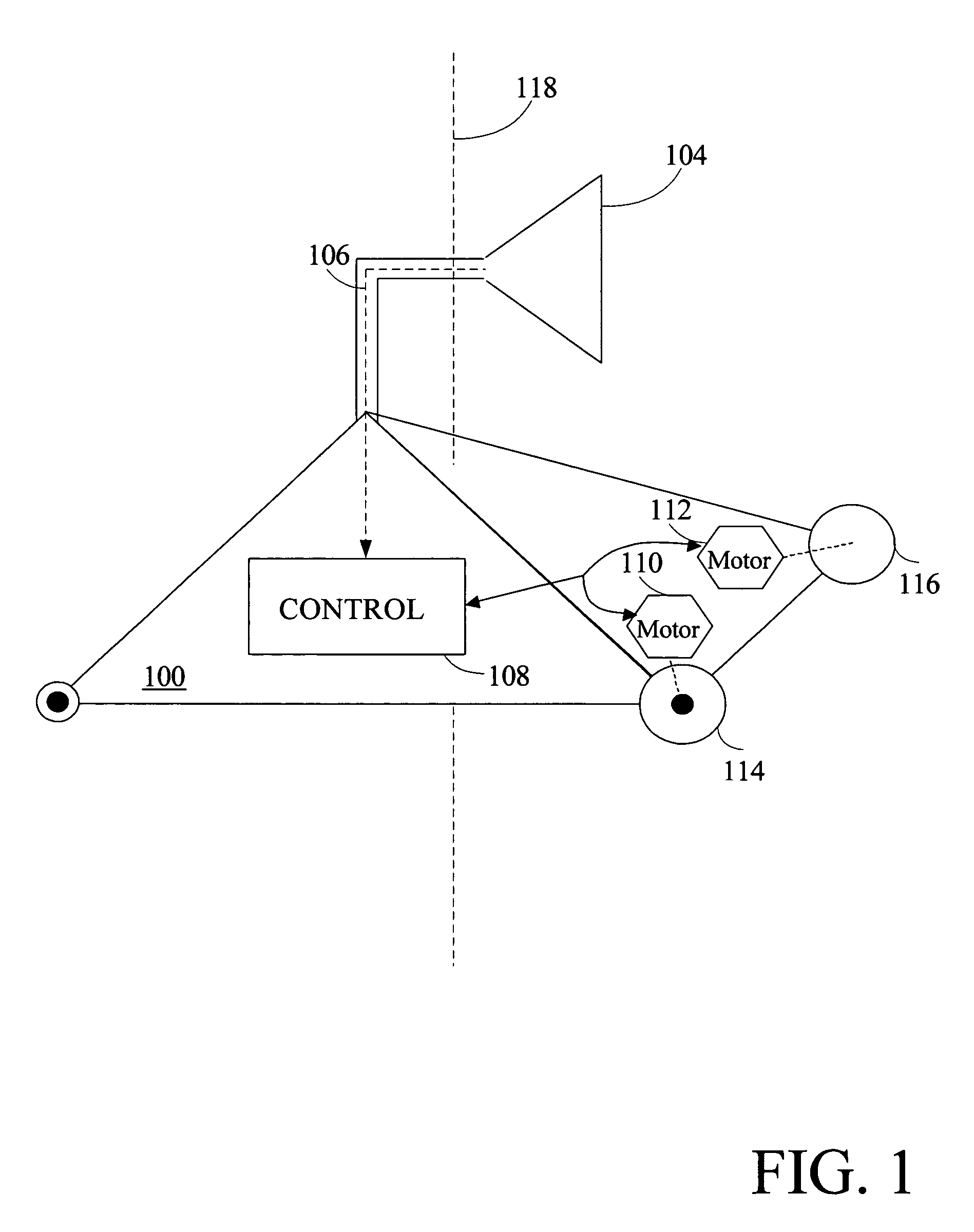
[0290]In Example 1 (Sequential), operation of the system is described where the system fuses measurements from two or more reliable sensors. In this example, data for a mobile robot is robustly fused. In the illustrated example, sensor B corresponds to a dead reckoning sensor, such as a wheel odometer, coupled to a robot, and measurement MB from sensor B is based on dead reckoning data, such as odometry measurements, relative to a reliable pre-existing robot pose estimate xold. Sensor C corresponds to a visual sensor, such as a camera coupled to the robot, and measurement MC from sensor C is based on visual estimates, such as visual measurements, of robot pose relative to a pre-existing map. For the purposes of this example, measurements MB and MC are always reliable. Other examples that will be described later illustrate process behavior in the presence of an unreliable measurement.

[0291]With reference to the exemplary environment of the apartment 1602 described earlier in connecti...

example 2

[0294]In Example 2 (Sequential), operation of the system is described in the context of one reliable sensor. In this example, sensor B corresponds to a dead reckoning sensor, such as a wheel odometer, coupled to a robot, and measurement MB from sensor B is based on dead reckoning data, such as odometry measurements, relative to a reliable pre-existing robot pose estimate xold. Sensor C corresponds to a visual sensor, such as a camera coupled to the robot, and measurement MC from sensor C is based on visual estimates, such as visual measurements, of robot pose relative to a pre-existing map. For the purposes of this example, measurement MB is considered reliable, and measurement MC is unreliable.

[0295]With reference to the exemplary environment of the apartment 1602 illustrated in FIG. 16, a previously estimated pose xold indicates that the previous position of the robot is relatively likely to correspond to a part of the apartment 1602 corresponding to the living room 1614 and relat...


PUM


Abstract

This invention is generally related to methods and apparatus that permit the measurements from a plurality of sensors to be combined or fused in a robust manner. For example, the sensors can correspond to sensors used by a mobile device, such as a robot, for localization and / or mapping. The measurements can be fused for estimation of a measurement, such as an estimation of a pose of a robot.

Description

RELATED APPLICATION[0001]This application claims the benefit under 35 U.S.C. §119(e) of U.S. Provisional Application No. 60 / 544,486, entitled “METHODS FOR ROBUST SENSOR FUSION,” filed Feb. 13, 2004, the entirety of which is hereby incorporated by reference.APPENDIX A[0002]Appendix A, which forms a part of this disclosure, is a list of commonly owned copending U.S. patent applications. Each one of the applications listed in Appendix A is hereby incorporated herein in its entirety by reference thereto.BACKGROUND[0003]1. Field of the Invention[0004]The invention generally relates to combining or fusing data from sensors. In particular, the invention relates to robust techniques for a robot of combining data that may include potentially unreliable data.[0005]2. Description of Related Art[0006]The problem of estimating a characteristic that cannot be known with certainty is common. For example, if sensor measurements with known statistical properties and correlated with the characteristi...

Claims


Application Information

Patent Timeline
Patent Type & Authority Patents(United States)
IPC IPC(8): G05B19/18B64C13/18G01C22/00G05D1/02G06F19/00G06V10/84
CPCG05D1/0246G05D1/0272G05D1/024G05D1/0242G05D1/0248G05D1/0255G05D1/0274G06V20/10G06V10/245G06V10/84G06F18/29
Inventor KARLSSON, LARS NIKLAS
Owner IROBOT CORP
Why Eureka
Try Eureka