Wall configuration of axial-flow machine, and gas turbine engine

a technology of axial flow machine and gas turbine engine, which is applied in the direction of machines/engines, stators, liquid fuel engines, etc., can solve the problems of pressure loss (energy loss), and achieve the effects of reducing loss, improving performance, and reducing loss

Active Publication Date: 2010-04-06
IHI CORP
View PDF21 Cites 52 Cited by
  • Summary
  • Abstract
  • Description
  • Claims
  • Application Information

AI Technical Summary

Benefits of technology

[0023]In the wall configuration of the flow machine of the invention, the loss by the secondary flow can be reduced.
[0024]Furthermore, in the gas turbine engine of the invention, the performance can be improved with the reduction of the loss due to the secondary flow.

Problems solved by technology

It is known that the secondary flow causes a pressure loss (energy loss).

Method used


Image

  • Wall configuration of axial-flow machine, and gas turbine engine
  • Wall configuration of axial-flow machine, and gas turbine engine
  • Wall configuration of axial-flow machine, and gas turbine engine

Examples


Embodiment Construction

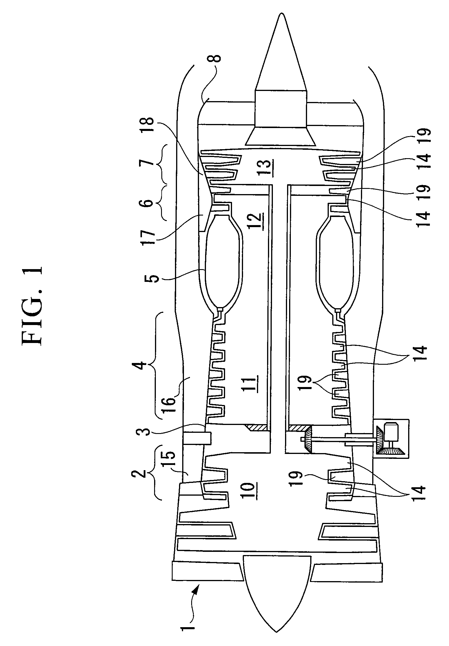
[0040]FIG. 1 is a schematic sectional view showing a gas turbine engine (turbo-fan engine) that is usable for an aircraft or the like, as an example of an axial-flow machine to which the present invention is applicable.

[0041]The gas turbine engine includes, for example, an air intake 1, a fan / low-pressure compressor 2, an exhaust fan duct 3, a high-pressure compressor 4, a combustion chamber 5, a high-pressure turbine 6, a low-pressure turbine 7, and an exhaust duct 8.

[0042]Each of the fan / low-pressure compressor 2, high-pressure compressor 4, high-pressure turbine 6, and low-pressure turbine 7 includes: a rotor having blades (rotor blades) 14 that are provided on the outer circumference of each of rotary drums 10, 11, 12, and 13 as a base and are circumferentially spaced apart from each other; and a stator having vanes (stator vanes) 19 that are provided on the inner circumference of each of annular casings 15, 16, 17, and 18 as a base and are circumferentially spaced apart from ea...


PUM


Abstract

A wall configuration of an axial-flow machine which can reduce the secondary flow loss is provided. A trough is formed between a blade and another blade in the blade row and extends in at least an axial direction of the blade row. The region where the trough is formed is axially between a leading edge and a trailing edge of the blade. A center line of the trough has a curvature in the same direction as a camber line of the blade. A maximum amplitude of the trough is located adjacent to an axial center of the blade or located axially between the axial center and the leading edge of the blade.

Description

CROSS REFERENCE TO RELATED APPLICATION[0001]The present application is a 35 U.S.C. §§ 371 national phase conversion of PCT / JP2005 / 017515, filed 22 Sept. 2005, which claims priority of Japanese Patent Application No.P2004-277114filed 24 Sept. 2004, which is herein incorporated by reference. The PCT International Application was published in the Japanese language.TECHNICAL FIELD[0002]The present invention relates to a wall configuration of a radial wall facing a flow path of an axial-flow machine.[0003]This application claims priority on Japanese Patent Application No. 2004-277114 filed Sep. 24, 2004, the contents of which are incorporated herein by reference.BACKGROUND ART[0004]In an axial-flow machine such as a gas turbine engine or the like having a blade row, inner and outer radial walls surround a flow path and a boundary layer grows on the wall. In the boundary layer on the wall, a secondary flow having a different velocity component from a main flow is generated due to, for exa...

Claims


Application Information

Patent Timeline
Patent Type & Authority Patents(United States)
IPC IPC(8): F01D9/02
CPCF01D5/143F05D2270/17F05D2250/71Y02T50/673F05D2250/70Y02T50/671Y02T50/60
Inventor AOTSUKA, MIZUHOHAMAZAKI, HIROSHITAKAHASHI, AKIRATANIMITSU, HARUYUKI
Owner IHI CORP
Why Eureka
Try Eureka