Internal combustion engine system having a power turbine with a broad efficiency range

a technology of power turbines and combustion engines, applied in the direction of machines/engines, stators, liquid fuel engines, etc., can solve the problems of significant impact of efficiency drop, system reliability is questioned, and the efficiency of systems is affected

Active Publication Date: 2010-04-13
DEERE & CO
View PDF12 Cites 21 Cited by
  • Summary
  • Abstract
  • Description
  • Claims
  • Application Information

AI Technical Summary

Problems solved by technology

A major impediment to maintaining efficiency over a broader range of operating conditions is a result of the incident angle with which the exhaust or heated gas flow is introduced to the periphery of the turbine wheel.
This is primarily due to an incident angle that is not optimum for the part throttle conditions.
The drop in efficiency significantly impacts part load performance characteristics of an engine system with which it is used and may ultimately influence the ability to flow air required for clean combustion characteristics.
However, such systems have been proven to questionable reliability, given the carbon laden nature of the gases passing through it and the requirement for a large plurality of vanes to be pivoted in precise unison.

Method used


Image

  • Internal combustion engine system having a power turbine with a broad efficiency range
  • Internal combustion engine system having a power turbine with a broad efficiency range
  • Internal combustion engine system having a power turbine with a broad efficiency range

Examples


Embodiment Construction

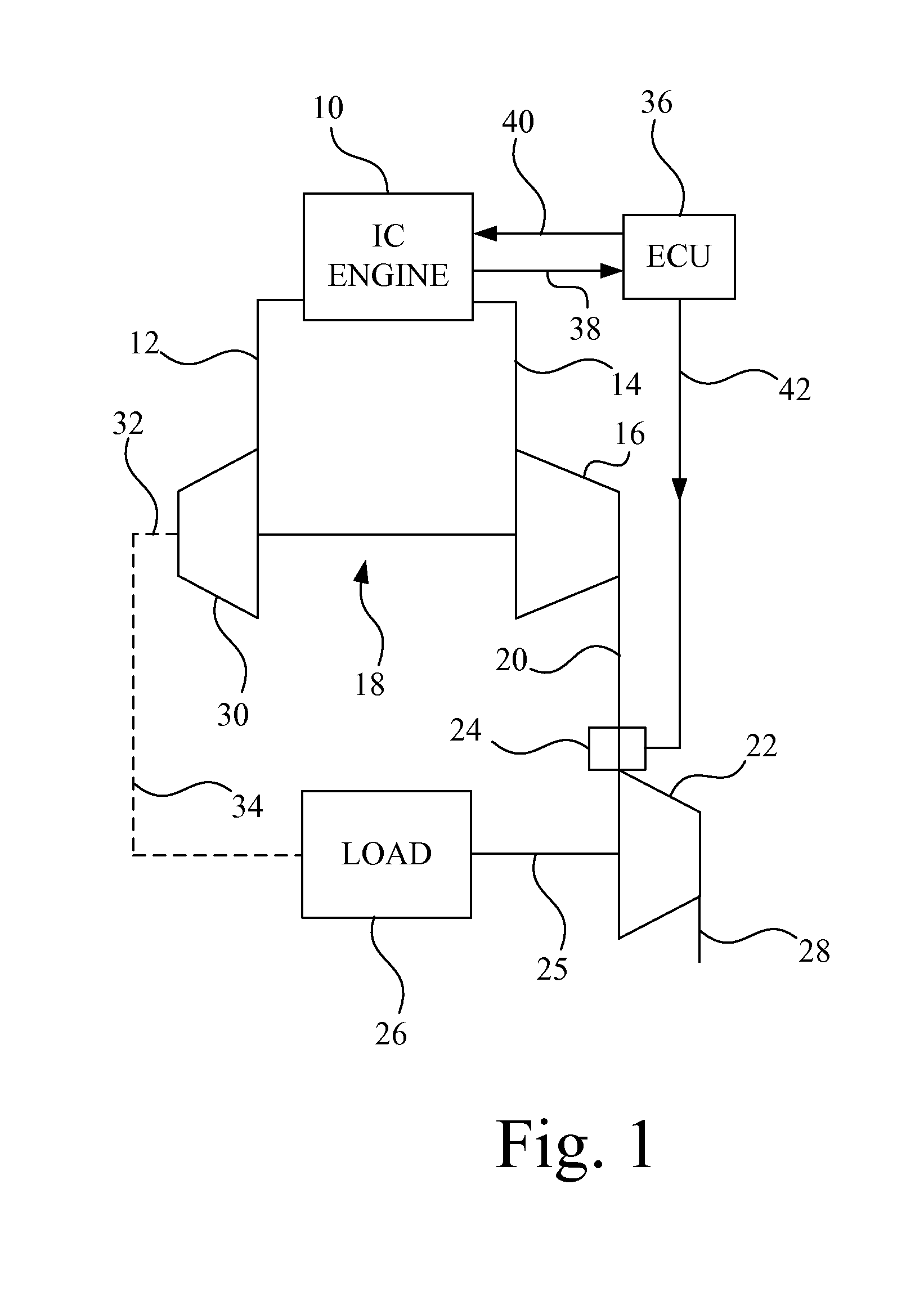
[0012]FIG. 1 shows an internal combustion engine system including an engine 10 producing a power output. Engine 10 may be provided in many different forms but, for the purposes of illustrating the invention, it is described as a reciprocating, air breathing internal combustion engine in which air is received from an inlet 12 and compressed in a cylinder or combustion chamber. Fuel is either mixed with the air prior to entry or within the combustion chamber. The resultant mixture is either ignited by an external source, such as a spark ignition, or by the heat of compression of the air, as in a diesel engine. Further combinations may be provided, such as homogenous charge compression ignition engines. It should be apparent to those skilled in the art that many different internal combustion engine types may be employed with the present invention.

[0013]The products of combustion from engine 10 are delivered to an exhaust 14 and from there to a turbine 16 of a turbocharger, generally in...


PUM


Abstract

An engine system incorporating an air breathing, reciprocating internal combustion engine having an inlet for air and an exhaust for products of combustion. A centripetal turbine receives products of the combustion and has a housing in which a turbine wheel is rotatable. The housing has first and second passages leading from the inlet to discrete, approximately 180°, portions of the circumference of the turbine wheel. The passages have fixed vanes adjacent the periphery of the turbine wheel and the angle of the vanes in one of the passages is different than those in the other so as to accommodate different power levels providing optimum approach angles between the gases passing the vanes and the blades of the turbine wheel. Flow through the passages is controlled by a flapper valve to direct it to one or the other or both passages depending upon the load factor for the engine.

Description

GOVERNMENT RIGHTS IN PATENT[0001]This invention was made with government support under contract no. DE-FC26-05NT42422 awarded by the Department of Energy. The United States government has certain rights in this invention.FIELD OF THE INVENTION[0002]The present invention relates to internal combustion engine systems and more specifically to engines having power turbines incorporated in the system.BACKGROUND OF THE INVENTION[0003]The first turbocharger was proposed by Alfred Buchi in 1905. The turbocharger began as a device to capture energy that was wasted in the exhaust system of a naturally aspirated engine by passing exhaust gases over a series of blades on a turbine wheel to produce a rotary power output. The turbine was connected to and drove a compressor to increase the charge density of an engine and therefore the power output. Since 1905, immense strides have been made in the turbo machinery field to improve the efficiency, flexibility and durability of individual components....

Claims


Application Information

Patent Timeline
Patent Type & Authority Patents(United States)
IPC IPC(8): F02D23/00F03B1/00F03B3/16F03D1/04
CPCF01D9/026F01D17/148F02C6/12F02B37/025F05D2220/40Y02T10/144Y02T10/12
Inventor WHITING, TODD MATHEWVUK, CARL THOMAS
Owner DEERE & CO
Why Eureka
Try Eureka