
Method of testing semiconductor apparatus

a technology of semiconductor apparatus and test method, which is applied in the direction of information storage, static storage, digital storage, etc., can solve the problems of memory malfunction, high cost, and high cost of semiconductor apparatus, and achieve high detection sensitivity of defective mode, improve detection sensitive, and improve the effect of snm defect detection

Inactive Publication Date: 2010-04-13
RENESAS ELECTRONICS CORP
View PDF4 Cites 2 Cited by
  • Summary
  • Abstract
  • Description
  • Claims
  • Application Information

AI Technical Summary

Benefits of technology

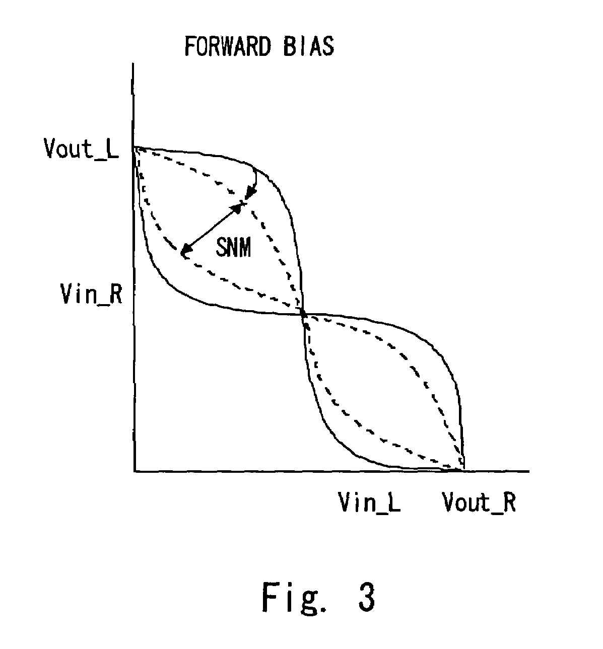
[0014]According to the embodiments of the present invention, a memory cell is tested with a forward bias by applying a positive electric potential to a P well if a field-effect transistor is an N type and by applying a negative electric potential to an N well if a field-effect transistor is a P type. It is thereby possible to test the memory cell with small SNM and improve the detection sensitively of an SNM defect. It is also possible to improve the detection sensitively of another defective mode which is hard to detect in normal condition by controlling a bias to be applied to each well independently of each other.
[0015]According to the present invention, it is possible to provide a method of testing a semiconductor apparatus which has a high detection sensitivity of the defective mode which becomes significant by a decrease in a threshold (or an increase in a cell current).

Problems solved by technology

In such a case, there is a problem that memory malfunctioning is likely to occur depending on the LSI use environment, that is, by a temperature or voltage change.
Defective modes include a write / read defect caused by the varying threshold of a field-effect transistor constituting a memory cell and an unstable operation caused by the deficiency of SNM, in addition to a leakage defect that has been a problem.
These defective modes are aggravated as miniaturization progresses, which raises a problem of a cost increase due to the need for a high-temperature / low-temperature test for reliable removal of a defective cell or the like.
Since the through current keeps flowing in a standby condition, the semiconductor apparatus has a standby defect.
However, the method taught by Shiomi only controls a threshold to be higher by applying a back bias.
Therefore, although it has a tentative effect that the memory cell which has leakage is easily identified, the method is incapable of detecting the defective mode that becomes more significant as the threshold of the field-effect transistor becomes lower (or a cell current becomes higher), such as an SNM defect.

Method used


Image

  • Method of testing semiconductor apparatus
  • Method of testing semiconductor apparatus
  • Method of testing semiconductor apparatus

Examples


Embodiment Construction

[0024]The invention will now be described herein with reference to illustrative embodiments. Those skilled in the art will recognize that many alternative embodiments can be accomplished using the teachings of the present invention and that the invention is not limited to the embodiments illustrated for explanatory purposes.

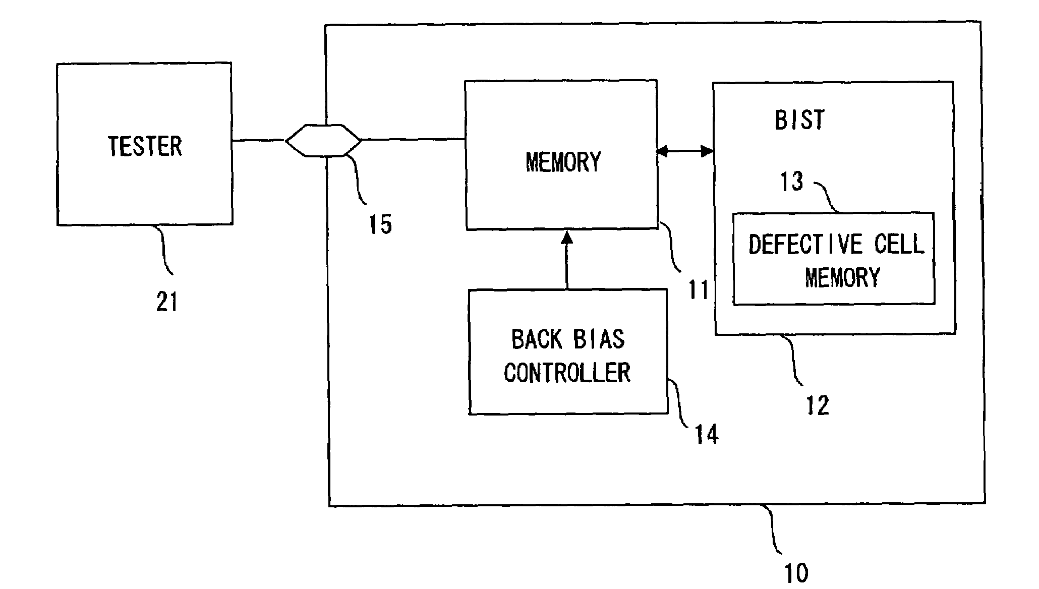
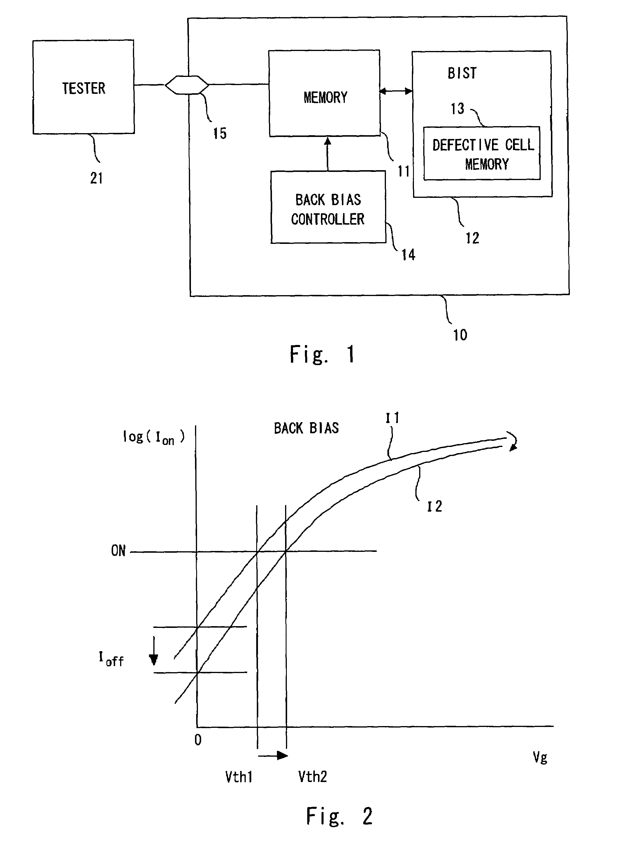
[0025]Exemplary embodiments of the present invention are described hereinafter in detail with reference to the drawings. FIG. 1 is a schematic diagram showing a semiconductor apparatus according to an embodiment of the present invention. A semiconductor apparatus 10 includes a memory 11, a BIST 12, a back bias control circuit 14, and a terminal 15 for test. The BIST 12 includes a defective cell memory 13 which stores a defective address when a defective cell is detected. The defective cell memory 13 may be placed outside of the BIST.

[0026]The back bias control circuit 14 controls the back bias of the N channel and P channel transistors that constitute a memory. I...


PUM


Abstract

A method of testing a semiconductor apparatus performs a function test of reading data from memory cells in SRAM by applying a potential lower than a GND potential to a backgate of an n-type MOS transistor with a drain connected with a storage node and a source connected with the GND potential. Then, the method performs a function test of reading data from memory cells by applying a potential higher than the GND potential to the backgate.

Description

BACKGROUND OF THE INVENTION[0001]1. Field of the Invention[0002]The present invention relates to a method of testing a semiconductor apparatus suitable for detecting a defective cell due to a defective standby current or SNM (static noise margin) deficiency.[0003]2. Description of Related Art[0004]Normally, when testing a memory cell such as RAM (Random Access Memory), a BIST (built in self-test) is performed (step S101), a fail bit is read (step S102), and a defective cell is replaced with a redundancy cell by cutting a fuse (step S103), as shown in FIG. 6.[0005]However, in some cases, a cell which places the border of a defective cell and a non-defective cell remains without being replaced. In such a case, there is a problem that memory malfunctioning is likely to occur depending on the LSI use environment, that is, by a temperature or voltage change. Defective modes include a write / read defect caused by the varying threshold of a field-effect transistor constituting a memory cell...

Claims


Application Information

Patent Timeline
Patent Type & Authority Patents(United States)
IPC IPC(8): G11C7/00
CPCG11C29/50G11C29/12005G11C11/41G11C2029/5002
Inventor AKIYAMA, NAOTO
Owner RENESAS ELECTRONICS CORP
Learn More