
Tracking system and label for use in conjunction therewith

a technology of tracking system and label, applied in the field of retail industry, can solve the problems of inability to absorb the production costs of individual label printing, sorting, packing and shipping, and the inability to use bar code systems, and achieve the effect of reducing production costs, reducing labor costs, and reducing production costs

Active Publication Date: 2010-04-13
AVERY DENNISON CORP
View PDF13 Cites 68 Cited by
  • Summary
  • Abstract
  • Description
  • Claims
  • Application Information

AI Technical Summary

Benefits of technology

[0057]It is yet still another object of the present invention to provide a product label as described above which includes a link code that allows for retrieval of the unique identification code by means other than RFID technology.

Problems solved by technology

However, as can be appreciated, the production costs associated with the printing, sorting, packing and shipping of individual labels (e.g., labor, equipment and facilities) are often too large for a product manufacturing facility to absorb.
As a result, many retail companies often out-source either a portion or all of their ticketing services to a specialist in the ticketing industry.
To the contrary, bar code systems are not typically used to uniquely identify individual articles of commerce from similar articles of commerce (i.e., item-level identification).
Because bar code systems are not designed for item-level identification, most commercially available supply chain management systems which utilize automated bar code systems have been limited to product tracking at either the carton-level or the pallet-level.
On the other hand, manufacturing facilities that install RFID labeling systems must invest in potentially expensive RFID equipment and infrastructure such as printers and scanners, and some factories may choose to delay that investment.
Also, as compared to bar codes which are relatively durable, RFID devices are vulnerable to damage causing corruption or loss of data.
To the contrary, traditional bar codes are directly exposed to outside elements which can compromise their integrity and, as a consequence, their functionality.
As a first drawback, participants in the retail supply chain often lack the significant capital that is required to purchase RFID equipment (e.g. RFID readers).
Without the necessary RFID equipment, these participants are unable to extract the unique identification code that is assigned to an RFID label.
As a second drawback, in the event that RFID chip 91 should malfunction (e.g., fail to operate as the result of either intentional or unintentional chip damage), participants in the retail supply chain are precluded from retrieving the data stored on the RFID label.
As a third drawback, in the event that RFID chip 91 has been tampered with (e.g., by an unscrupulous customer seeking to circumvent the security applications of RFID technology), participants in the retail supply chain are precluded from retrieving the data stored on the RFID label.
Stated another way, RFID technology does not presently afford a means for verifying the authenticity of data provided by an RFID label.
As can be appreciated, the inability for participants in the supply chain to retrieve the data stored on an RFID label detrimentally affects the supply chain in two ways.
First, participants in the supply chain are unable to retrieve (i.e., download) crucial product information from a central database (e.g., retrieve real-time tracking information).
Second, participants in the supply chain are unable to supply (i.e., upload) pertinent product information to a central database (e.g., provide data that is used to update the real-time tracking information).

Method used


Image

  • Tracking system and label for use in conjunction therewith
  • Tracking system and label for use in conjunction therewith
  • Tracking system and label for use in conjunction therewith

Examples


Embodiment Construction

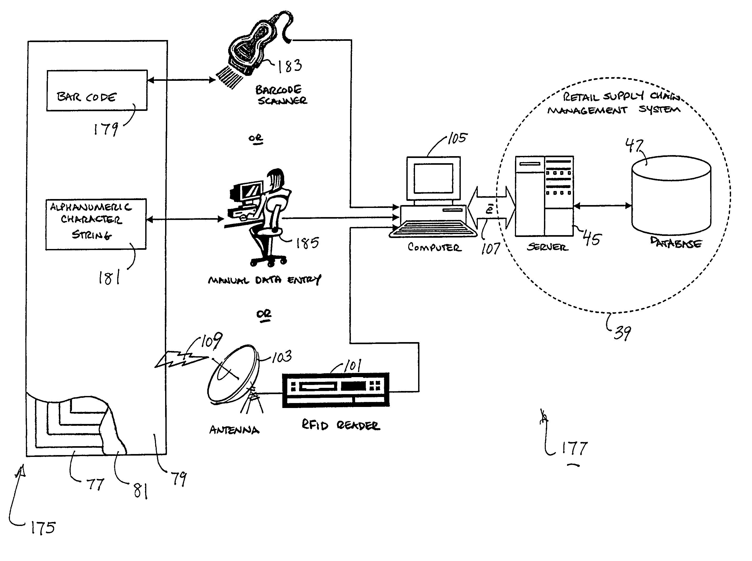
[0072]Referring now to FIG. 5, there is shown an article tracking system which is constructed according to the teachings of the present invention and represented generally by reference numeral 99. As will be described further below, article tracking system 99 is designed to wirelessly transmit data from a conventional RFID label (e.g., RFID label 75) to a retail supply chain management system 39.

[0073]In tracking system 99, an RFID label 75 is shown affixed to an article of commerce A. As can be appreciated, RFID label 75 is preferably programmed to include a unique identification code (e.g., using the electronic product code system) which can be retrieved using radio frequency technology.

[0074]As can be seen in FIG. 5, a bar code 100 is printed on facestock 79 of label 75. However, it should be noted that bar code 100 is not an alternative representation of the unique identification code that is programmed onto IC chip 93. Rather, bar code 100 is provided to supply data of a consid...


PUM


Abstract

A hybrid label is provided with a unique product identification code which can be retrieved using multiple independent processes. In one embodiment, the hybrid label includes an RFID inlay and a printable face sheet which are secured together by a layer of adhesive material. The RFID inlay includes an integrated circuit chip which is programmed with the unique product identification code. The printable face sheet includes a bar code and an alphanumeric character string, each of which is configured to represent the same identification code. A product tracking system designed in accordance with the hybrid label is able to extract the unique identification code from the label and, in turn, associate the identification code with a designated bundle of data records which is located in an external database. The product tracking system can retrieve the identification code through the use of either RFID technology, bar code technology or manual data entry. The ability to monitor an individual article of commerce throughout the retail supply chain provides the system with, among other things, item-level tracking, anti-counterfeit, anti-diversion, security and article return applications.

Description

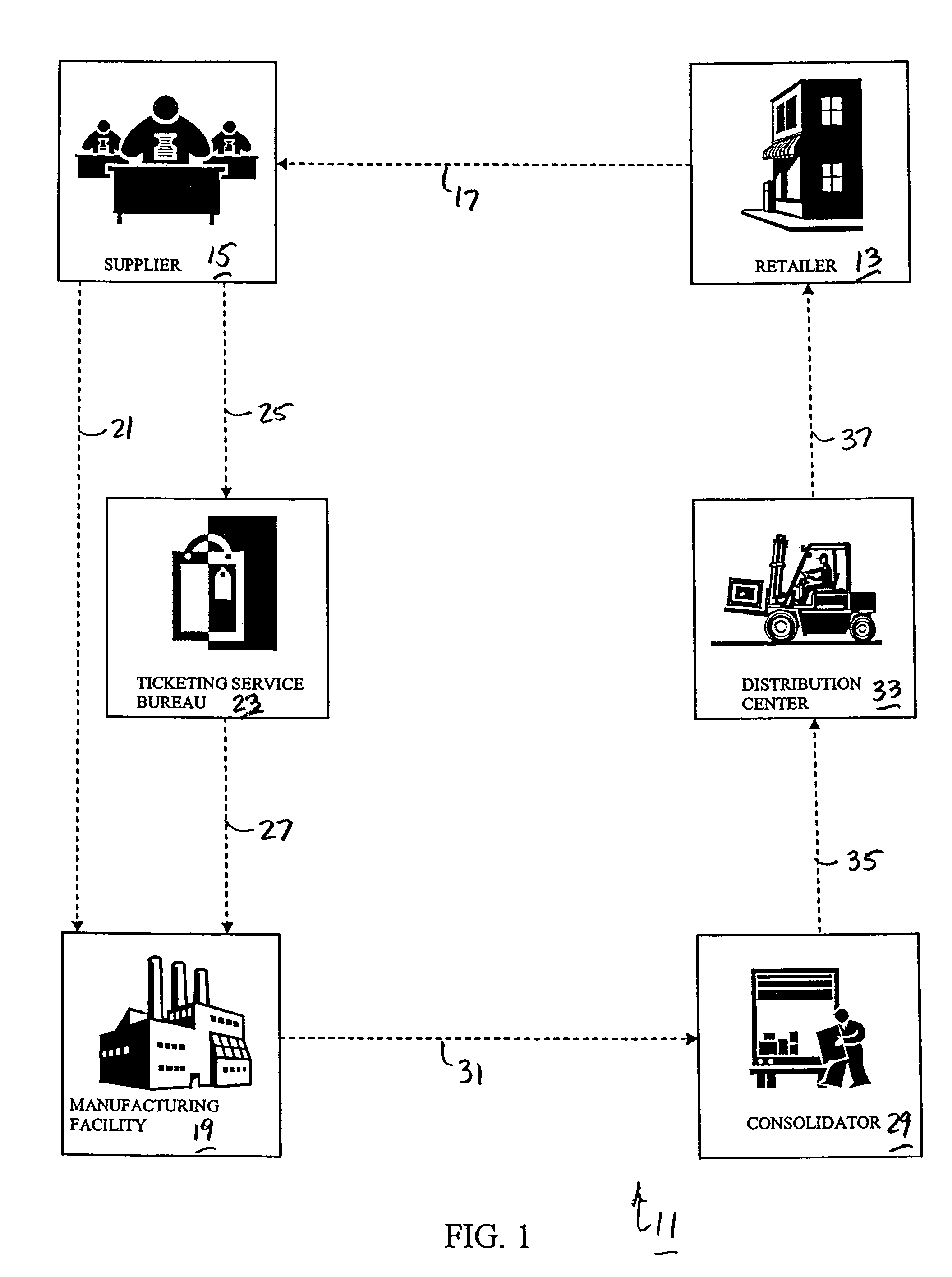
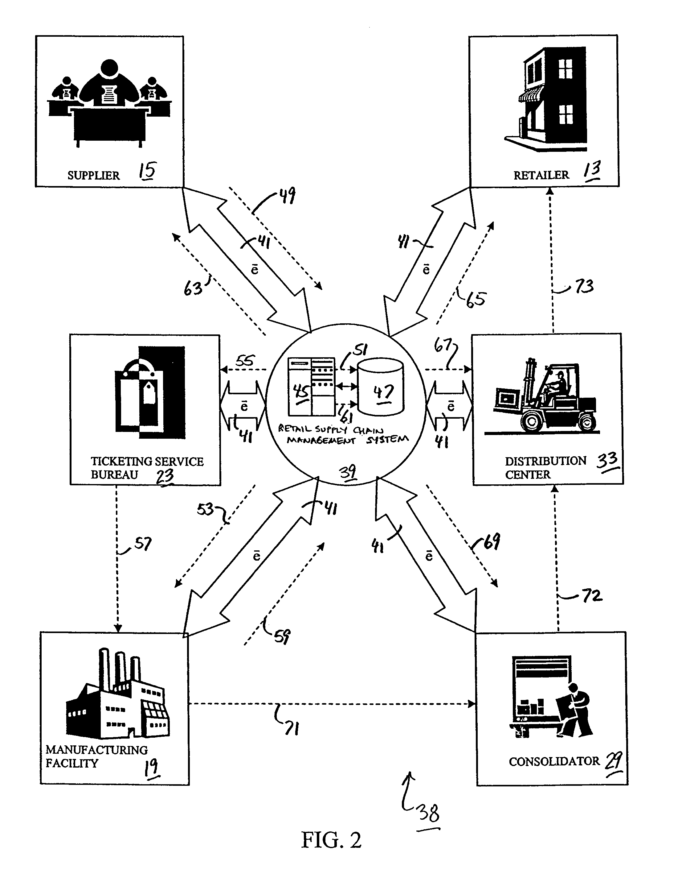
CROSS-REFERENCE TO RELATED APPLICATIONS[0001]The present application claims the benefit under 35 U.S.C. 119(e) of U.S. provisional Patent Application Ser. No. 60 / 694,164, filed Jun. 27, 2005, the disclosure of which is incorporated herein by reference.BACKGROUND OF THE INVENTION[0002]The present invention relates generally to the retail industry and more particularly to the use of radio frequency identification (RFID) technology in the retail industry.[0003]An article of commerce is typically delivered from a supplier (e.g., a brand owner or vendor) to a buyer (e.g., a retailer or brand owner) through a multi-stepped process which is commonly referred to in the art as the retail supply chain. Specifically, referring now to FIG. 1, there is shown a simplified block diagram of one common version of the retail supply chain, the retail supply chain being identified generally by reference numeral 11. In the first step of supply chain 11, a retailer 13 places a purchase order (i.e., an or...

Claims


Application Information

Patent Timeline
Patent Type & Authority Patents(United States)
IPC IPC(8): G06Q10/00
CPCG06Q10/08G06Q10/087G06Q10/0833
Inventor LEUNG, ANDY S.CLEMENS, ALI HOBALU, SANJAY
Owner AVERY DENNISON CORP
Learn More