Eureka AIR delivers breakthrough ideas for toughest innovation challenges, trusted by R&D personnel around the world.

High performance sights

a high-performance, sighting technology, applied in the field of sports equipment, can solve the problems of limited use of bows and firearms for hunting, and achieve the effect of efficient and convenient us

Inactive Publication Date: 2010-04-20
WILSON KEITH W
View PDF15 Cites 10 Cited by
  • Summary
  • Abstract
  • Description
  • Claims
  • Application Information

AI Technical Summary

Benefits of technology

"The present invention is about bow and firearm sights that use fiber optic materials and tritium to provide illumination in low-light or no-light conditions. The invention includes unique bow sights with shaped sight windows and fiber optic sight pins that can utilize tritium. The invention is efficient, easy to use, and cost-effective. The technical effects of the invention include improved sighting in low-light or no-light conditions, improved durability, and improved user experience."

Problems solved by technology

Heretofore, the use of bows and firearms for hunting has been limited in the early morning or evening hours when natural light is low.

Method used


Image

  • High performance sights
  • High performance sights
  • High performance sights

Examples


first embodiment

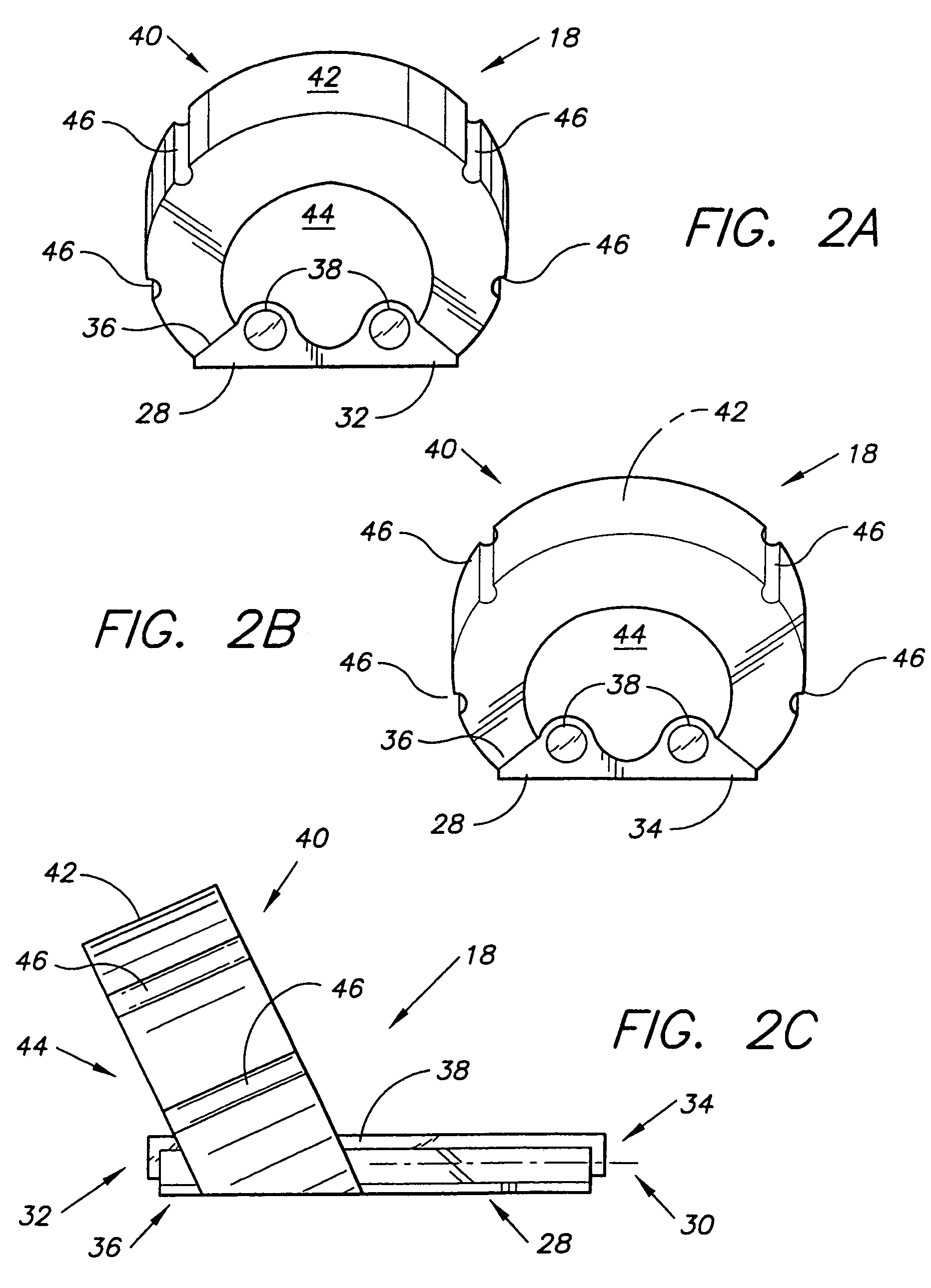
[0064]Turning to FIGS. 2A to 2C, a transparent rear bow sight 18 has a rectangular planar opaque base 28 having a longitudinal axis 30 (FIG. 2C), a front end 32 and a rear end 34. The base 28 is preferably made from aircraft grade aluminum 6061-T6, then anodized for yet further protection against weathering elements. The base anodized 36 contains partially embedded on its top surface a parallel pair of straight colored fiber optic pins 38 which are stiff clear plastic compositions containing tritium. The sight pins 38 can vary in diameter, as in colors. The smaller diameters of sight pins are the preferred. As to the alternative colors of the fiber optic sight pins, and tritium night sights, many alternatives can apply, however; yellow and green have proven to perform the best, and are the preferred. Alternatively, a single colored fiber optic pin could be used, but the accuracy of aiming is enhanced by using two parallel fiber optic pins. The base 28 can be another metal or any typ...

second embodiment

[0066]In FIGS. 3A, 3B and 3C, a rear transparent bow sight 48 is illustrated. The aperture 50 has been shaped to dip between the colored fiber optic pins 52 which are now inclined upward toward the sight window 40 and joined to a U-shaped configuration 54. These pins are made from flexible plastic compositions. It has been found that the inclination of the pins 52 on the rectangular opaque base 28 aids in a better view without a part of the optic sight 48 obstructing the hunter's view.

third embodiment

[0067]In FIGS. 4A, 4B and 4C, a rear transparent bow sight 56 is illustrated. The notches 46 have been reduced to three in number to accommodate a division of three strands, wherein two strands are a minimum for this type of sight. It has been found that the lesser the division of strands of a bowstring, the better the visibility through the sight. The base 58 is configured as a cylindrical rod 60 supporting a planar portion 62, and the rod 60 has been shifted to the rear end of the bow sight 56.


PUM


Abstract

Bow and fixed firearm sights, employing fiber optic materials and tritium to provide illumination during periods of low-light, and no-light. As contemplated the bow sights are usable with or without an elastic alignment cord attached to the bow riser / limb and / or forward cable system of a compound bow. In its simplest form the bow sight comprises a bow sight having an opaque base, a transparent housing disposed on and integral with the base, a sight window having peripheral notches therearound and a fiber optic pin embedded in the transparent housing.

Description

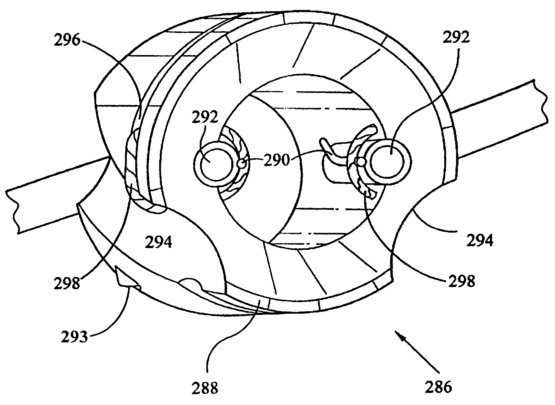
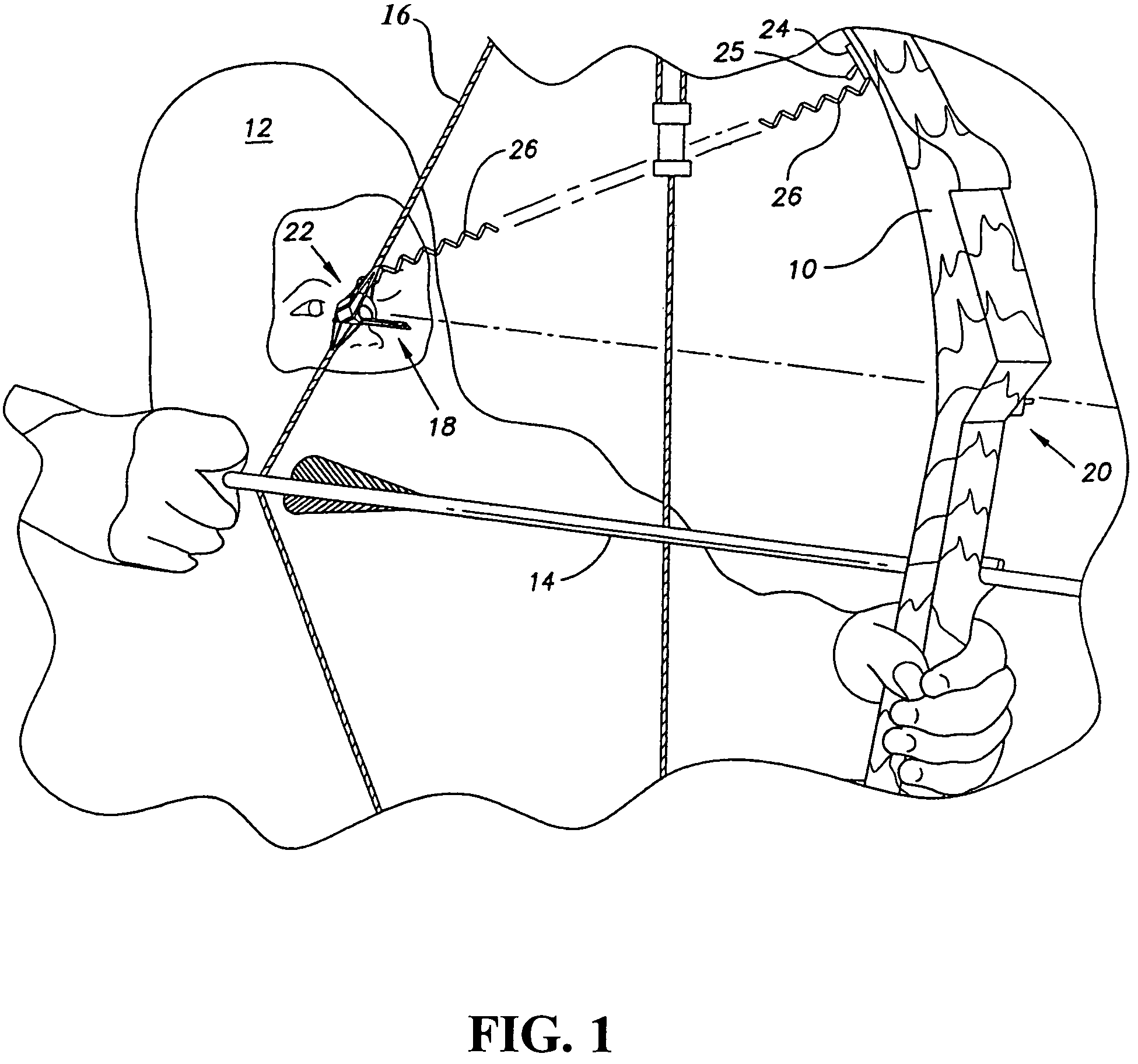
BACKGROUND OF THE INVENTION[0001]1. Field of the Invention[0002]The present invention generally relates to sports equipment. More specifically, the present invention is drawn to high-performance sighting devices for target-practice for hunting bows and fixed sight firearms.[0003]2. Description of the Related Art[0004]Utilizing a bow, or firearm for hunting and / or target shooting is very popular to a growing segment of the sporting population. Heretofore, the use of bows and firearms for hunting has been limited in the early morning or evening hours when natural light is low. Since most jurisdictions prohibit the use of flashlights or the like, bow and firearm hunting has been virtually non-existent without high performance sights at these hours. An efficient bow or firearm sight that is extremely effective in normal daylight hours and, in low-light or, in no-light scenarios would certainly be a welcome addition to the art.[0005]The related art, as identified and cited in the accompa...

Claims


Application Information

Patent Timeline
Patent Type & Authority Patents(United States)
IPC IPC(8): F41G1/467
CPCF41G1/01F41G1/467F41G1/32F41G1/10
Inventor WILSON, KEITH W.
Owner WILSON KEITH W
Why Eureka
Eureka Blog
Learn More