Vessel spray cleaning device

a cleaning device and spray head technology, applied in the direction of movable spraying apparatus, cleaning process and apparatus, chemistry apparatus and processes, etc., can solve the problems of safety hazards and difficulty in mechanically driving upwardly oriented spray head, and achieve the effect of efficient and convenient use of spray cleaning

Active Publication Date: 2017-08-08
SPRAYING SYST
View PDF11 Cites 0 Cited by
  • Summary
  • Abstract
  • Description
  • Claims
  • Application Information

AI Technical Summary

Benefits of technology

[0005]It is an object of the present invention to provide a more efficient and easy to use spray cleaning device for cleaning storage vessels, such as wine barrels, from an underside access opening.
[0006]Another object is to provide a vessel spray cleaning device as characterized above that is more easily adaptable for use with vessels supported at different elevations with respect to the floor.
[0007]A further object is to provide a vessel cleaning device of the foregoing type having a mechanically driven rotary spray head adapted for more reliable operation.
[0008]Still a further object is to provide a vessel cleaning device of the above kind in which the cleaning liquid supply is substantially separated from the spray head drive in a manner that reduces sealing requirements for the drive.
[0009]Another object is to provide a vessel cleaning spray device as described above which is relatively simple and economical in construction and lends itself to easy and more reliable usage.

Problems solved by technology

Since the spray head must be inserted from an underside of barrel, it can be cumbersome to position the spray head into the barrel and to effectively drive the spray head, particularly when space below the barrel is limited.
Again, due to the limited space, it can be difficult to mechanically drive the upwardly oriented spray head while directing pressurized liquid to the spray head.
Moreover, when the drive is driven by an electrical motor, safety hazards can exist due to the wet environment about the barrels during cleaning.

Method used


Image

  • Vessel spray cleaning device
  • Vessel spray cleaning device
  • Vessel spray cleaning device

Examples


Embodiment Construction

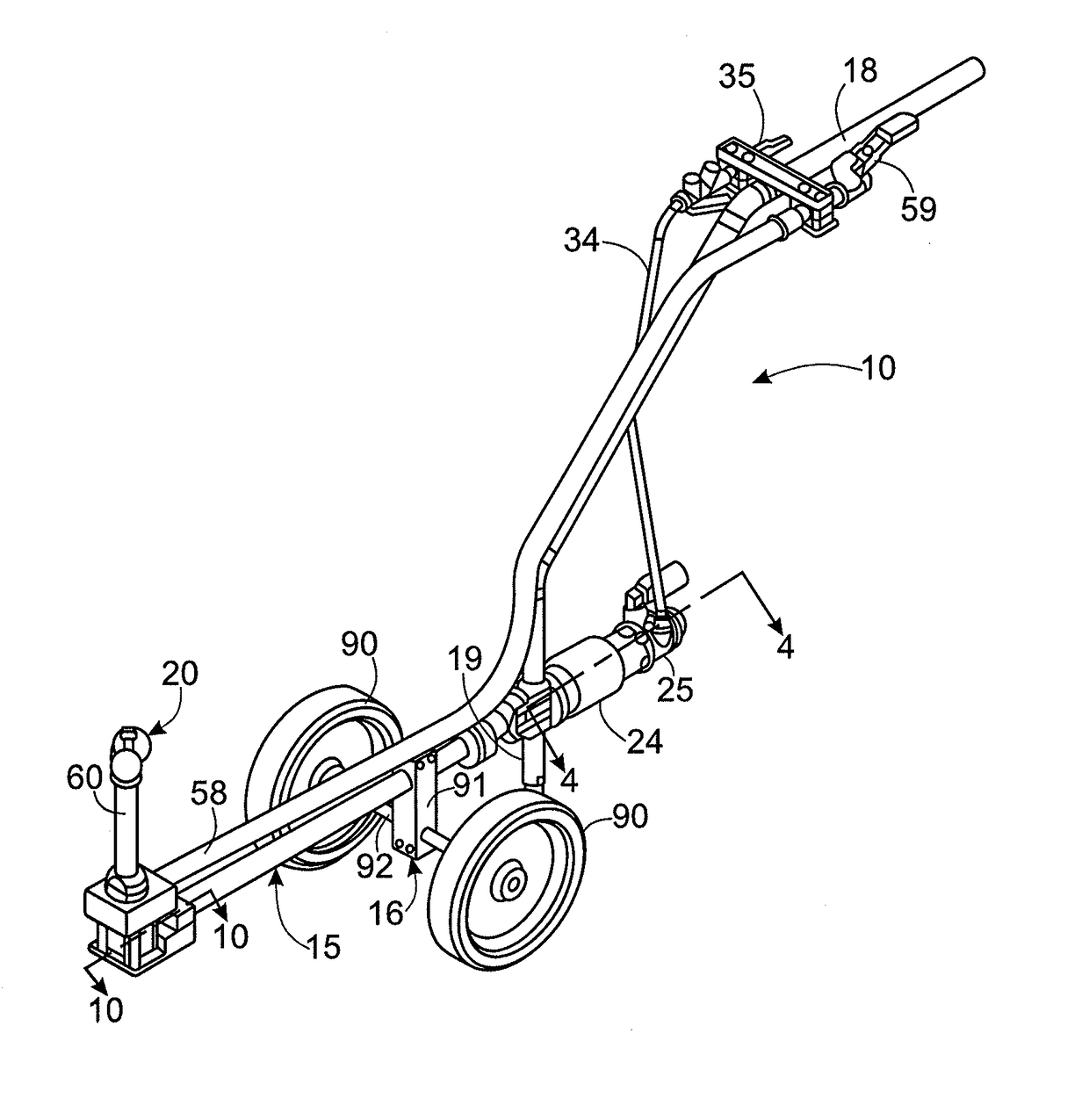
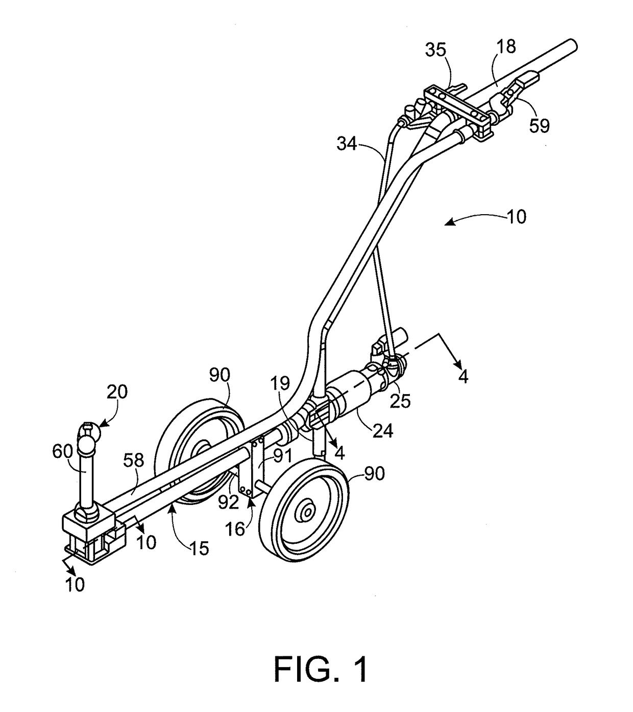
[0025]Referring now more particularly to the drawings, there is shown an illustrative vessel spray cleaning device 10 in accordance with the invention, which in this case is depicted for use in cleaning of a wine barrel 11 supported on a rack 12 in elevated relation to a floor as depicted in FIG. 3. The wine barrel 11 is of a conventional type, having closed ends and a generally cylindrical outwardly bowed sidewall with an access opening 14 centrally located in the sidewall that is plugged during processing of wine. Following completion of processing and removal of the contents from the barrel, the barrel 11 must be thoroughly cleaned, and for this purpose, it is rotated on its rack 12 with the axis opening 14 in the underside of the barrel 11.

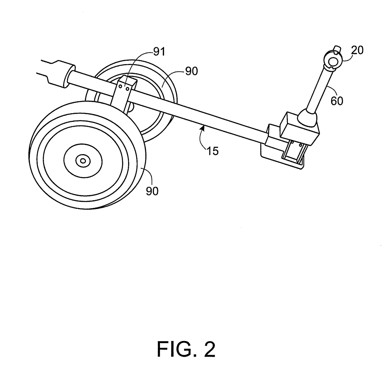
[0026]The illustrated cleaning device 10 basically comprises an elongated frame in the form of a straight cylindrical extension tube 15, preferably made of stainless steel, supported by a wheeled carriage 16 and having an elongated elevated ha...


PUM


Abstract

A spray cleaning device for cleaning the interior of a vessel or the like through an access opening in an underside thereof. The cleaning device includes a wheeled carriage positionable in selected relation to a vessel to be cleaned, an elongated frame having a central drive shaft extending along its length, and a rotatable spray head supported in an upstanding relation to a downstream end of said elongated housing for rotation about multiple axes. The elongated frame is pivotably supported by said wheeled carriage for selective positioning of the spray head within the vessel to be cleaned, and the spray head has a liquid supply which communicates with a liquid inlet to an upstanding support thereof downstream of the central drive shaft so said liquid is not transmitted along the drive shaft.

Description

CROSS-REFERENCE TO RELATED APPLICATION[0001]This patent application claims the benefit of the U.S. Provisional Patent Application No. 61 / 931,751, filed. Jan. 27, 2014, which is incorporated by reference.FIELD OF THE INVENTION[0002]The present invention relates generally to spray cleaning devises for cleaning liquid storage and processing vessels, barrels, tanks, and like containers, that are supported by cradles or other support apparatus with a closable access opening or drain hole in an underside thereof for enabling entry of a spray head of a cleaning device into the interior of the vessel and drainage of the cleaning liquids from the vessel.BACKGROUND OF THE INVENTION[0003]It is known to support processing vessels in elevated relation to the floor to facilitate cleaning of the interior of the vessel from an opening in a bottom side. In wine production, for example, wine is processed in large generally cylindrical barrels that are supported during processing on cradle like racks ...

Claims


Application Information

Patent Timeline
Patent Type & Authority Patents(United States)
IPC IPC(8): B08B9/093B08B9/08B05B3/02B05B13/06B05B15/68
CPCB08B9/0813B05B3/027B05B3/028B05B13/0636B08B9/0826B08B9/0936
Inventor BUHL, BOLAND
Owner SPRAYING SYST
Why Eureka
Try Eureka