Locking aerosol dispenser

a dispenser and aerosol technology, applied in the field of plastic aerosol dispensers, can solve the problems of requiring more force than the user, affecting the unlocked position, and overly complex design of the mold,

Active Publication Date: 2010-04-20
PRECISION VALVE CORP
View PDF7 Cites 51 Cited by
  • Summary
  • Abstract
  • Description
  • Claims
  • Application Information

AI Technical Summary

Benefits of technology

[0006]The present invention is intended to provide an aerosol valve actuator having a top and a bottom portion, the top portion being rotatable with respect to the bottom portion between a first position for actuating the aerosol valve and a second position where the aerosol valve cannot be actuated. The aerosol valve is actuated by depressing the entire top portion as a unit in a vertical direction with respect to the bottom portion. A click post and a flexible clicking rib provide a single click in each direction of rotation of the top portion, so as to indicate the actuator rotational position in a non-confusing manner to consumers who might otherwise be confused by multiple clicks in each direction of rotation. The clicking post has a configuration and alignment to cause the clicking rib to pass on opposite sides of the clicking post for opposite directions of rotation and to provide a pronounced clicking sound.
[0007]Further, stop flanges on the bottom portion of the actuator, and support flanges for connecting flanges on the top portion of the actuator, interact to stop rotation of the top portion of the actuator in each of its rotational directions as soon as the single click in that direction has occurred. This also helps to avoid consumer confusion, and assures alignment of the top and bottom portions for dispensing.
[0008]Additionally, the lower portion of the actuator has a plurality of plastic spring members that interact with a plurality of spring-biasing members extending from the upper portion of the actuator only when the top portion has been rotated to its first position. In that position, the spring-biasing members overlie, contact and slightly depress the plastic spring members in a non-actuating manner to prevent rattling between the top and bottom portions of the actuator, and to assure even in the presence of an aerosol valve with short stem height that the actuator top portion will be returned to its full upward position following product dispensing so that the top portion can then be rotated to the non-dispensing position.

Problems solved by technology

Some of these designs are overly complex to mold, while others require more force than desirable for the user to operate between the inoperative and operative positions.
Still other designs in the unlocked position may not, following valve actuation, adequately return the top portion of the actuator upwardly to its rotatable position when used with aerosol valves having shorter stem heights due to normal variations in stem heights, etc.
Such designs when used with shorter stem heights may also result in rattling between the top and bottom actuator portions to imply a flimsiness to the consumer.
Additional designs are not sufficiently robust and are vulnerable to damage to their parts and operation due to excessive top loads from misuse, handling, shipping, etc.
Such mechanisms, however, are often overly complex and may provide multiple clicks with multiple clicking mechanisms when rotating between such positions, so that the consumer may be confused as to the status and operation of the actuator.
Such mechanisms may also involve a considerable angular rotation of the actuator parts, which may further confuse the consumer.

Method used


Image

  • Locking aerosol dispenser
  • Locking aerosol dispenser
  • Locking aerosol dispenser

Examples


Embodiment Construction

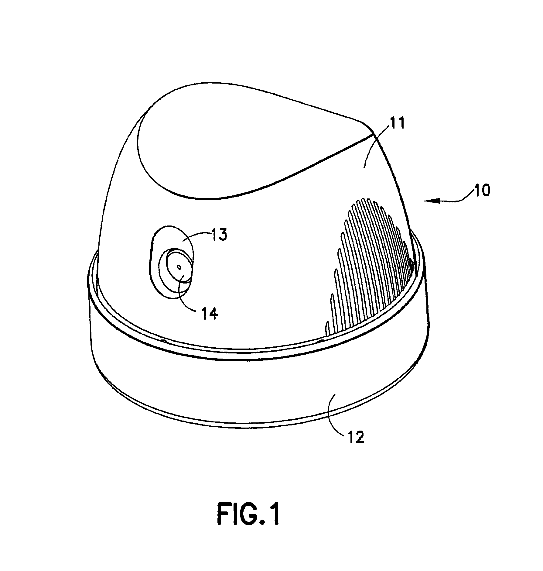
[0019]Referring to FIG. 1, aerosol dispenser 10 of the present invention is illustrated as assembled and in its unlocked actuating position. Actuator 10 has top portion 11 which is mounted on and rotatable with respect to bottom portion 12. Bottom portion 12 is mountable on top of an aerosol product container with an upstanding aerosol valve stem (not shown). Actuator top portion 11 has a front opening 13 which aligns with product nozzle 14 when the dispenser 10 is in its unlocked actuating position. The entire top portion 11 may be vertically depressed as a unit with respect to the bottom portion 12 to actuate the aerosol vertical valve stem and valve in the unlocked actuating position of dispenser 10. When the top portion 11 is rotated with respect to bottom portion 12 a small rotational distance away from the actuating position, top portion 11 can no longer be vertically depressed, and the aerosol valve stem and valve thus can no longer be actuated.

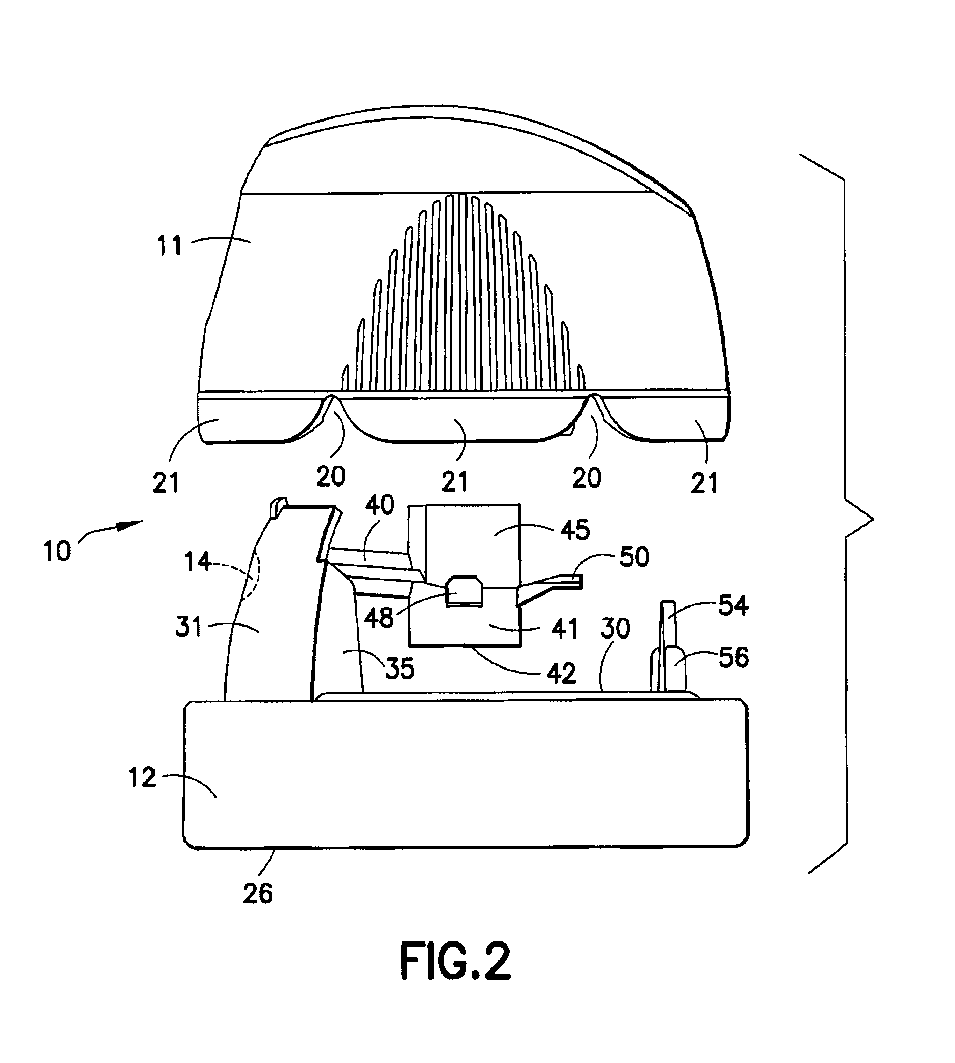
[0020]FIGS. 2, 3A and 3B show t...


PUM


Abstract

An aerosol valve actuator with a top portion rotatable on a bottom portion. The entire top portion in one rotatable position is depressible vertically to actuate the valve. A click post and clicking rib provide a single click in each direction of rotation. Flanges on top and bottom portions interact to stop rotation as soon as each click occurs. Plastic springs interact with spring biasing members only when the top portion is in actuating position, and assure return of the actuator top portion to full upward position for rotation after actuation of even a short-stemmed valve. Downwardly extending flexible connecting flanges connect the actuator top and bottom portions. The top portion has a lower periphery with a plurality of upwardly extending indentations to overlie lateral ribs in the lower portion in actuation position. The top and bottom portions have interfitting cylinders to stabilize the top portion and maintain verticality.

Description

FIELD OF THE INVENTION[0001]The present invention relates to plastic aerosol dispensers of the type often referred to as spray dome dispensers or actuators. More particularly, the present invention relates to such a dispenser having a top portion mounted on and rotatable with respect to a bottom portion between a first operative position for aerosol valve actuation and a second inoperative position in which the aerosol valve cannot be actuated.BACKGROUND OF THE INVENTION[0002]Prior art locking aerosol dispensers have existed for years and have had many different structural designs of interrelating parts. Some of these designs are overly complex to mold, while others require more force than desirable for the user to operate between the inoperative and operative positions.[0003]Still other designs in the unlocked position may not, following valve actuation, adequately return the top portion of the actuator upwardly to its rotatable position when used with aerosol valves having shorter...

Claims


Application Information

Patent Timeline
Patent Type & Authority Patents(United States)
IPC IPC(8): B65D83/14
CPCB65D83/205B65D83/16B65D83/22B65D83/206
Inventor HYGEMA, TERRY L.
Owner PRECISION VALVE CORP
Why Eureka
Try Eureka