Illuminated eyeglass assembly

a technology of eyeglasses and components, applied in the direction of spectacles/goggles, instruments, light supporting devices, etc., can solve the problems of unduly adjusting, limiting the number of people who will actually use, and bulky devices and awkward to wear, etc., to prolong the overall useful life of the eyeglass assembly

Active Publication Date: 2010-04-20
WATERS IND INC
View PDF28 Cites 65 Cited by
  • Summary
  • Abstract
  • Description
  • Claims
  • Application Information

AI Technical Summary

Benefits of technology

[0015]Each integral lighting assembly of the present invention also includes a power source and a switch mechanism. The power source may include one or more dry cell batteries, and in one preferred embodiment, the power source comprises a plurality of replaceable dry cell batteries, thereby

Problems solved by technology

While this device achieves the desired result of providing a source of illumination in the proximity of the user which may be directed by the movement of the user's head, the device is bulky and awkward to wear, due to the unbalance in weight caused by the penlight, thereby requiring the user to unduly readjust the eyeglasses into an operative position.
In addition, the presence of the penlight on the outer surface of the arm of the eyeglasses detracts from the overall appearance of the eyeglasses, and thus, the user.
It is believed that most persons who require eyeglasses to enhance their vision prefer not to attract additional attention to the fact that they require glasses, thus, a device which further detracts from the overall appearance of a pair of eyeglasses is likely to limit the number of people who will actually utilize it.
This again results in an unbalanced overall device, which may result in discomfort to the user.
Additionally, this device includes a separate power and/or switch mechanism which is attached to the lighting apparatus by an external cord or wire which, once again, detracts from the overall appearance of the device and the user, as well as being a source of further discomfort.
While a number of these devices incorporate a lighting apparatus on both arms of the pair of eyeglasses, thus overcoming t

Method used


Image

  • Illuminated eyeglass assembly
  • Illuminated eyeglass assembly
  • Illuminated eyeglass assembly

Examples


Embodiment Construction

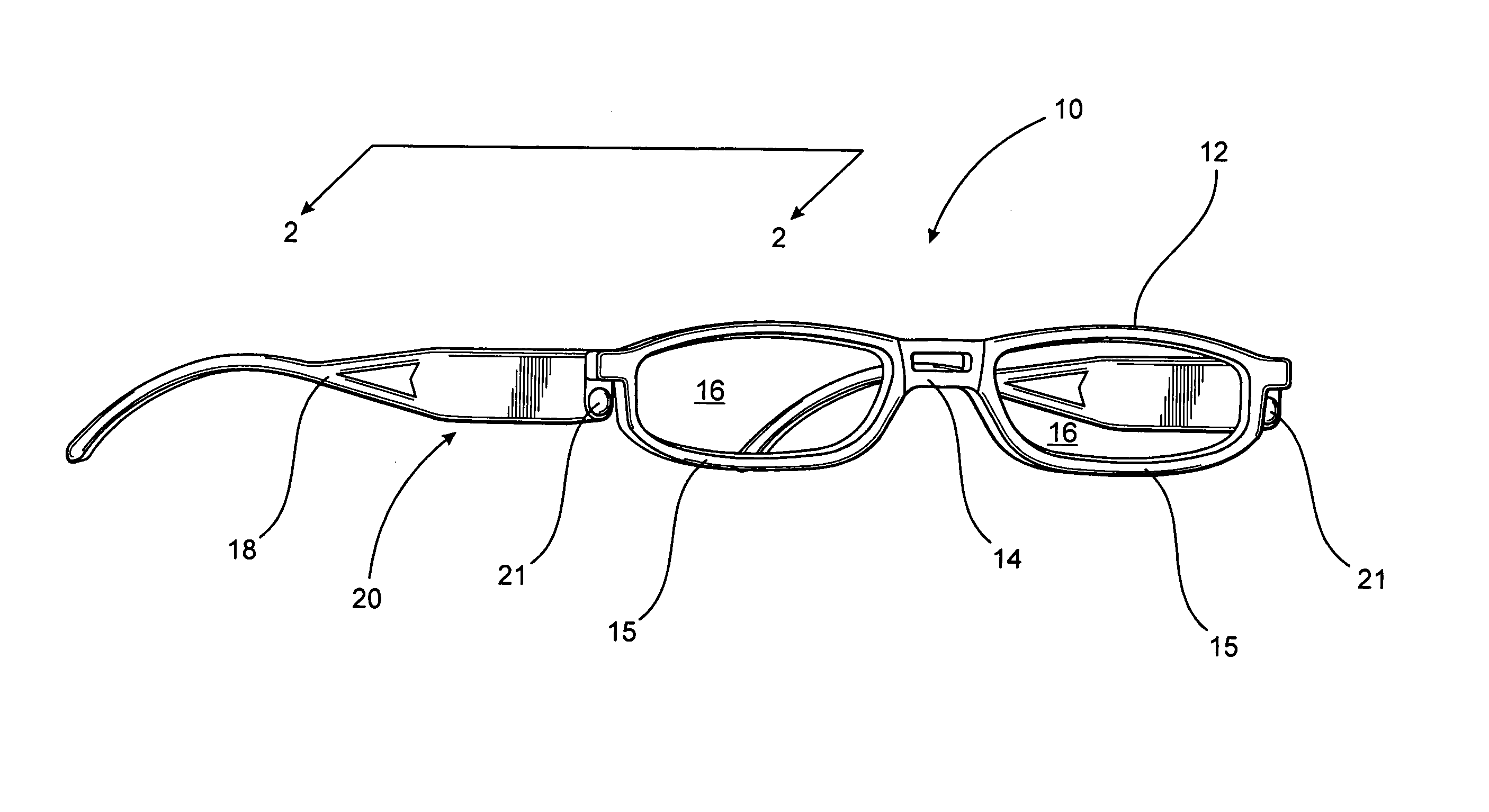
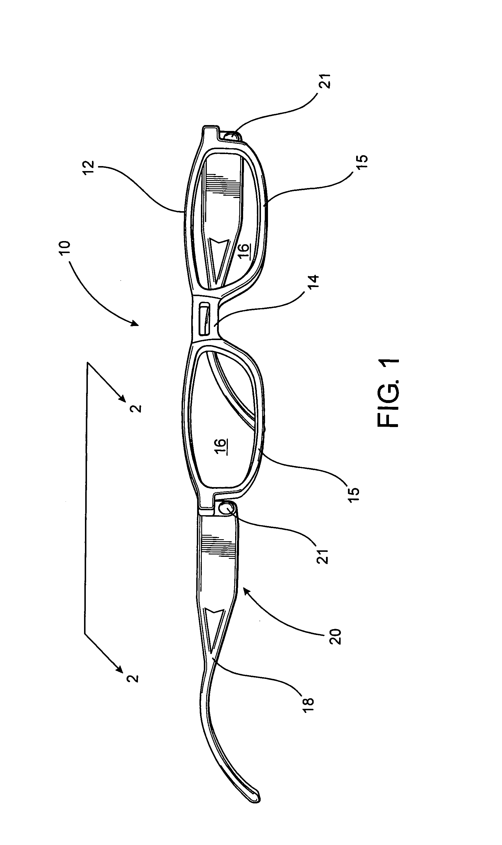
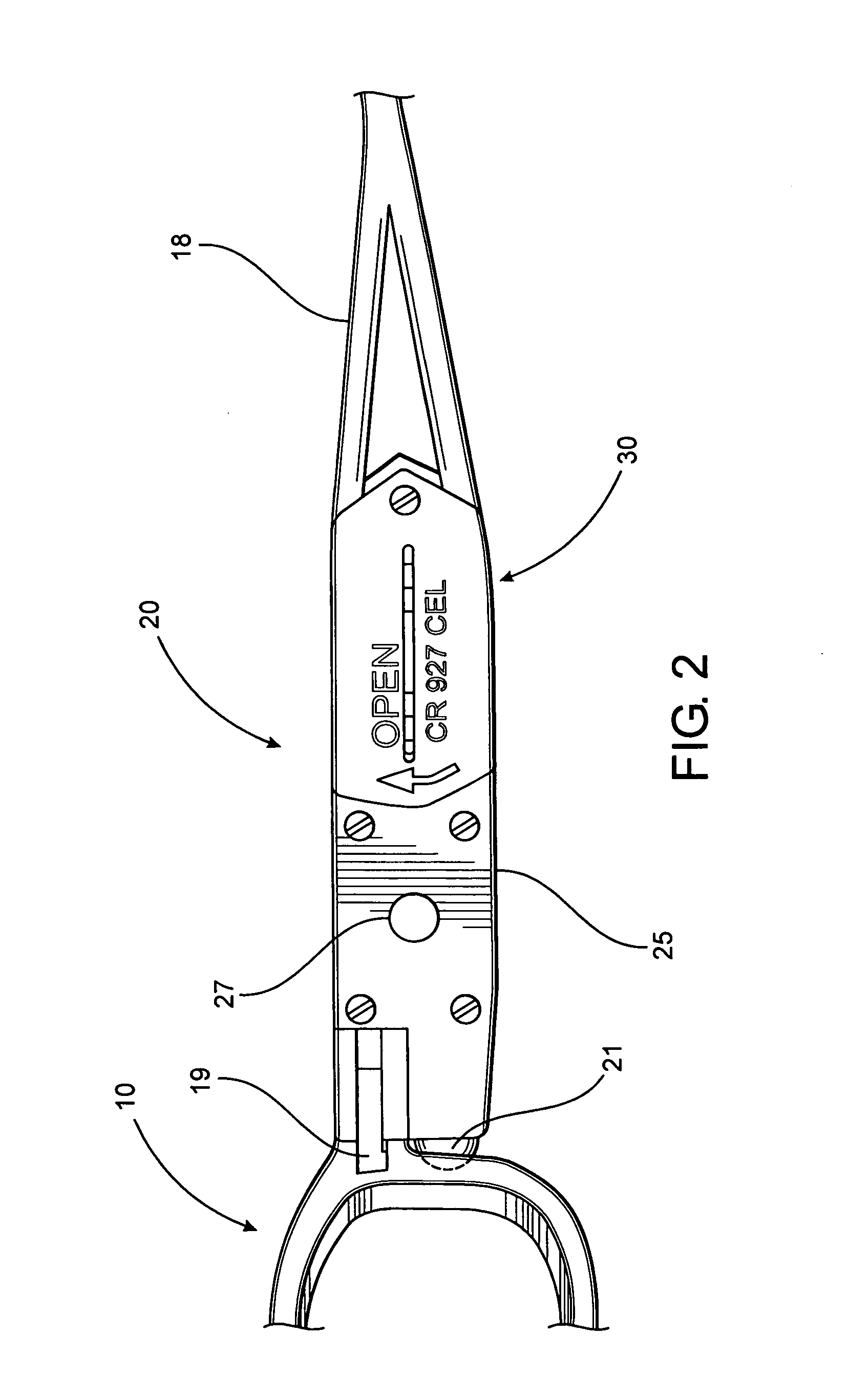
[0032]As indicated above, the present invention is directed to an illuminated eyeglass assembly with an integral lighting apparatus, generally shown as 10 throughout the figures. The illuminated eyeglass assembly 10 includes a frame12 having a nosepiece 14 and, in at least one embodiment, a pair of lens support members 15. In the embodiment of FIG. 1, the lens support members 15 are structured to substantially surround the periphery of each of a pair of lenses 16. Additionally, as illustrated in FIG. 2, an interconnect 19 is provided proximate a distal portion of each lens support member 15 such that each of a pair of temple members 18 may be interconnected to the frame 12. The interconnect 19, in at least one embodiment, comprises a hinged or pivot type of connection such that the temple members 18 may be disposed in a folded orientation for storage. In an alternate embodiment, the interconnects 19 may provide for a rigid connection of the temple members 18 to the frame 12. The len...


PUM


Abstract

An illuminated eyeglass assembly includes one or more temple members having an integral lighting assembly structured and disposed to provide an illumination region proximate a user, for example, to illuminate an item within an arm's length of the user. Each integral light assembly includes at least one light source interconnected to a power source via a switch mechanism. Each of the light sources produce a light beam, and the light sources are structured and disposed such that the light beams provide an illumination region immediately proximate the user, thereby permitting the user to perceptively view an item in a low light environment, such as, to permit the user to read menu or a check in a restaurant or nightclub. A system is provided to retrofit an existing eyeglass assembly with one or more temple member having an integral lighting assembly.

Description

BACKGROUND OF THE INVENTION[0001]1. Field of the Invention[0002]The present invention is directed to an illuminated eyeglass assembly comprising one or more integral lighting assembly structured and disposed to generate an illumination region to an area immediately proximate a user, where sufficient illumination is provided to enable the user to perceptively view an item in a low light environment.[0003]2. Description of the Related Art[0004]Eyeglasses have been utilized for a myriad of purposes throughout the years. One of the more common applications include prescription eyeglasses which many people require so as to be able to see clearly, and in more extreme cases, in order to allow a person to be able to see at all. Another common application for eyeglasses include standardized reading glasses which include lenses designed to provide a specific overall degree of magnification to objects which are viewed through them. Additionally, many people have at least one pair of sunglasses...

Claims


Application Information

Patent Timeline
IPC IPC(8): G02C1/00F21V21/084
CPCG02C11/04
Inventor BEINER, EDWARD
Owner WATERS IND INC
Why Eureka
Try Eureka