Instrumented take-up unit and related control method

a control method and instrument technology, applied in the direction of gearing control, gearing elements, gearing, etc., can solve the problems of a belt failure or a failure of the belt-tensioning or chain-tensioning device that may be anticipated, and achieve the effect of easy and rapid adjustmen

Inactive Publication Date: 2010-04-20
AB SKF
View PDF109 Cites 14 Cited by
  • Summary
  • Abstract
  • Description
  • Claims
  • Application Information

AI Technical Summary

Benefits of technology

[0008]In some embodiments, the system may include a belt-tensioning or chain-tensioning device by which the belt or chain tension may be easily and rapidly adjusted. The system may also include a belt-tensioning or a chain-tensioning device that may constantly monitor the tension of the belt, the wear of the belt and the correct functioning of the tensioning device. In certain embodiments, a belt failure or a failure of the belt-tensioning or chain-tensioning device may be anticipated.

Problems solved by technology

In certain embodiments, a belt failure or a failure of the belt-tensioning or chain-tensioning device may be anticipated.

Method used


Image

  • Instrumented take-up unit and related control method
  • Instrumented take-up unit and related control method
  • Instrumented take-up unit and related control method

Examples


Embodiment Construction

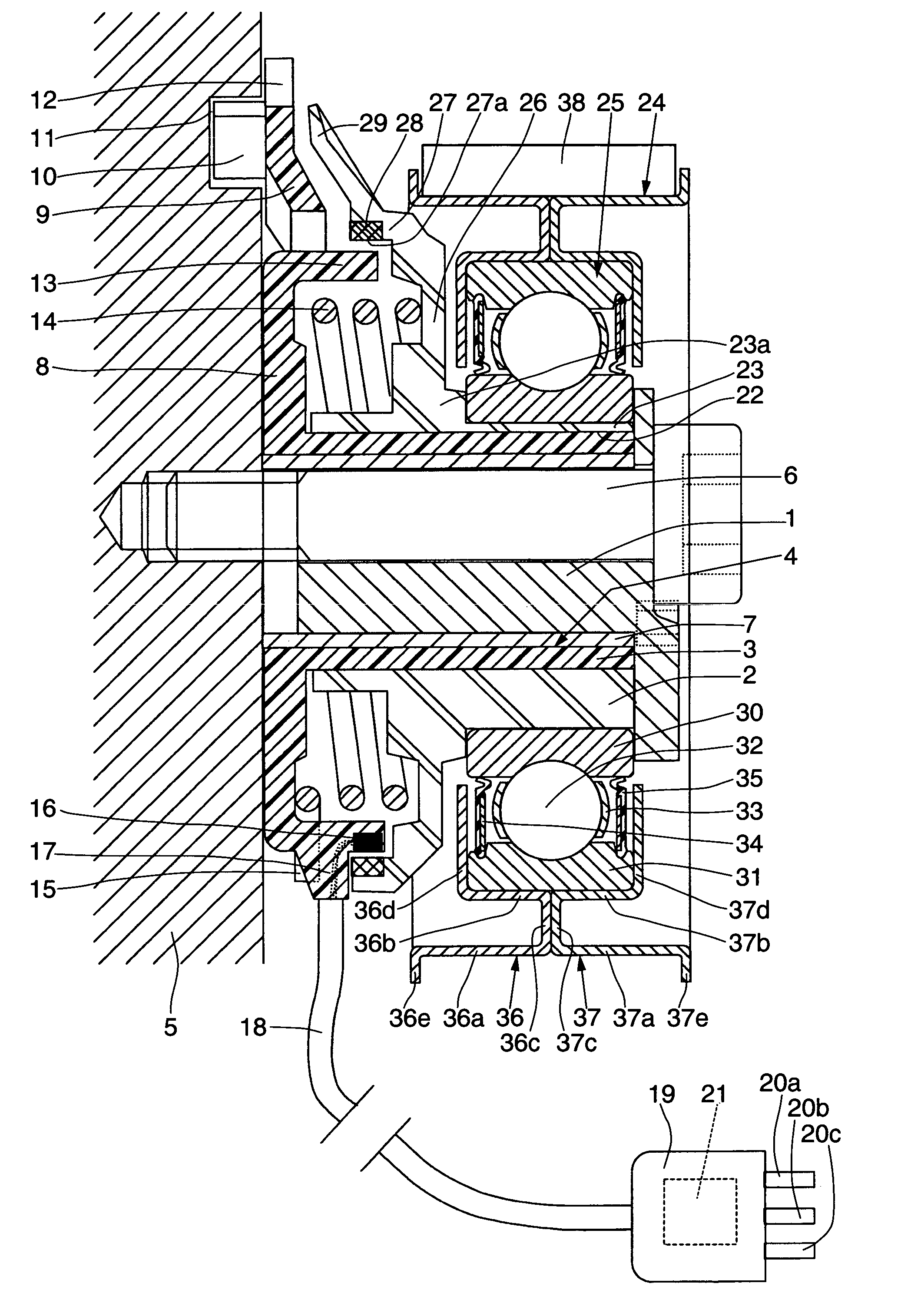
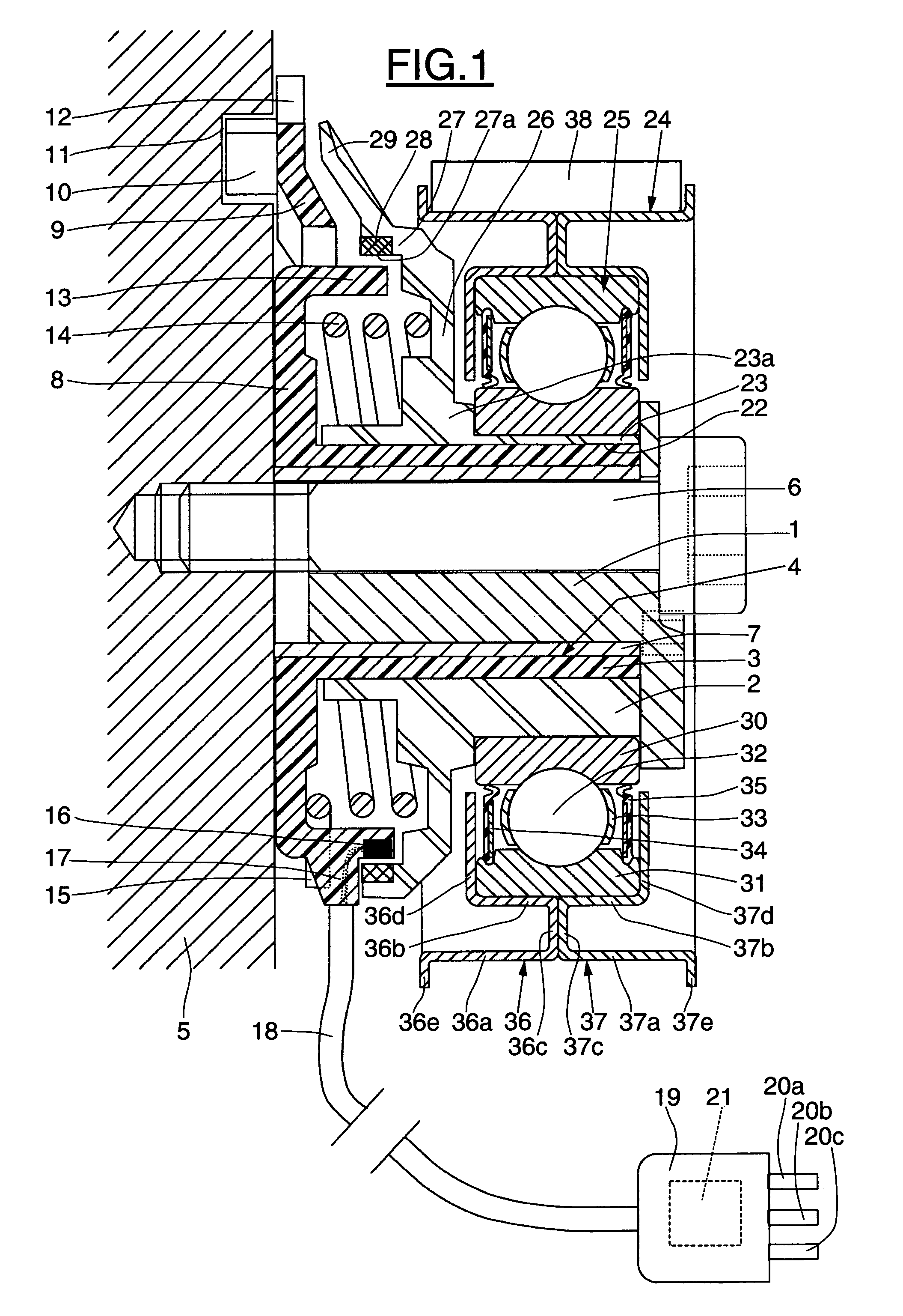
[0026]An embodiment of a tensioning device is depicted in FIG. 1. A tensioning device may include an adjusting cam 1 and a moving element. The moving element may include a working cam 2 mounted with rotational capability on the adjusting cam 1 by a tubular bushing 3 of a fixed bracket 4. The tubular bushing 3 forms a plain bearing.

[0027]An adjusting cam 1 may be fixed on a block 5 by means of a screw 6. The adjusting cam 1 may pivot relative to the block 5 when the screw 6 is loosened. Fastening the screw 6 may immobilize the cam 1.

[0028]The bracket 4 may include a cylindrical metal insert 7 positioned between the cam 1 and the tubular bushing 3. The metal insert 7 and the tubular bushing 3 are joined together by any appropriate means including, but not limited to, molding the tubular bushing 3 by casting the tubular bushing on the metal insert 7. The bracket 4 may include a plate forming a substantially flat base 8. The plate may attach perpendicularly to the tubular bushing 3 and ...


PUM


Abstract

The invention concerns a device for tensioning belts or chains that may include a fixed support; a moving element that may move relative to the fixed support and designed to be in contact with the belt or the chain; and an actuator designed to exert a permanent tensioning force between the mobile equipment and the fixed support. The device may also include a sensor unit to monitor parameters of angular displacement of the moving element relative to the fixed support.

Description

BACKGROUND OF THE INVENTION[0001]1. Field of the Invention[0002]The present invention generally relates to a belt-tensioning or a chain-tensioning device designed to ensure a suitable tension of a belt or chain. In particular, embodiments relate to systems and methods for ensuring a suitable tension of a belt or chain in a tension device in an automotive vehicle.[0003]2. Brief Description of the Related Art[0004]A tensioning device generally comprises a fixed bracket and a moving part, in the form of a cam or a swivel arm, mounted with rotational capability on the fixed bracket. A pulley is mounted in idle arrangement on the moving part by means of a rolling bearing and is intended to be brought into contact with the belt. A spring exerts a tension force between the bracket and the moving part, causing the pulley to make contact with the belt with a suitable belt tension. The moving part is mounted with adjustment capability on the bracket so as to be able to adjust the tension forc...

Claims


Application Information

Patent Timeline
Patent Type & Authority Patents(United States)
IPC IPC(8): F16H7/12F16H7/10F16H7/08F16H61/12
CPCF16H7/1281F16H7/1263F16H61/12F16H2007/081F16H2061/1208F16H2007/0876F16H2007/0891F16H2007/0893F16H2007/0861
Inventor MESSAGE, OLIVIERPONSON, FREDERIC
Owner AB SKF
Why Eureka
Try Eureka