Arrangement and Method for Radio-Frequency (RF) High Power Generation

a radio frequency and high power generation technology, applied in the direction of high frequency amplifiers, power amplifiers, amplifiers, etc., can solve the problems of increasing the complexity of the system, increasing the risk of failure, and low rf power output per transistor chip, so as to reduce the power loss of rf output, reduce the risk of failure, and reduce the cost

Inactive Publication Date: 2016-11-03
OOO SIEMENS
View PDF8 Cites 0 Cited by
  • Summary
  • Abstract
  • Description
  • Claims
  • Application Information

AI Technical Summary

Benefits of technology

[0010]In view of the foregoing, it is an object of the present invention to provide an arrangement and a method for RF high power generation that overcome the above mentioned problems. In particular, it is an object of the present invention to provide a cost effective, easy to handle assembly, which can be adjusted automatically, even after assembly. A reduction of RF output power loss, arising from events, such as aging of components and / or changes in connection lines length, are prevented and a maximum output power from the power combiner should be reachable. The disclosed arrangement and method provide the ability to adjust the output signals of components, particularly after assembly of components, is flexible, at any time, easy and without much effort, such that power losses at the output of a power combiner are reduced.
[0012]The disclosed arrangement for RF high power generation provides a cost effective, easy to handle assembly, which can be adjusted automatically to optimize the power output, even after assembly. A reduction of RF output power loss, arising from events, such as aging of components and / or changes in connection lines length, can be prevented and a maximum output power from the power combiner can be reached using the at least one RF switch and the at least one directional coupler for adjustment of electrical parameters. The output signals of the at least two power amplifier modules can be changed and optimized / synchronized, particularly after assembly of the arrangement, is flexible at any time, easily and without much effort. As a result, power losses at the output of the power combiner are reduced.
[0023]The method can be an automatic method, particularly controlled by a computer, and / or a manual method, particularly during production or maintenance. The ability to use the arrangement in accordance with the disclosed embodiments of the present invention and the method in an automated manner, also allows adjustments during the use of the arrangement, for example, necessary due to changes by aging effects of components. It is possible to adjust the arrangement easily and rapidly after exchanges, for example, of connection lines during maintenance. The high output RF power of the arrangement can be received continuously or preserved with time, and power losses can be avoided or at least reduced. The method can be repeated after a period of time, particularly at regularly time intervals. The advantages in connection with the described method for RF high power generation in accordance with the present invention are similar to the previously, in connection with the arrangement for RF high power generation, described advantages and vice versa.

Problems solved by technology

One disadvantage of transistor technology is a low RF power output per transistor chip, in the range of up to 1.5 kW power output at 500 MHz frequency.
An aggregation of transistors in a single power amplifier (PA) based, for example, on push- pull or a balanced kind of topology, can increase the complexity of the system and increases the risk of failure.
Due to different length and properties, each of the transmission lines introduces an individual power loss and signal phase shift to the arrangement.
It causes additional power losses, reduces the overall output RF power and can lead to overheating of amplifiers.
After the system is once assembled, it can hardly be adjusted.
Deviations of electronic components, such as by aging, cannot be compensated for and increase losses.
Additional devices, such as numerous directional couplers, are necessary and have to be installed in each RF module output branch, thereby increasing costs and complexity.

Method used


Image

  • Arrangement and Method for Radio-Frequency (RF) High Power Generation
  • Arrangement and Method for Radio-Frequency (RF) High Power Generation
  • Arrangement and Method for Radio-Frequency (RF) High Power Generation

Examples


Embodiment Construction

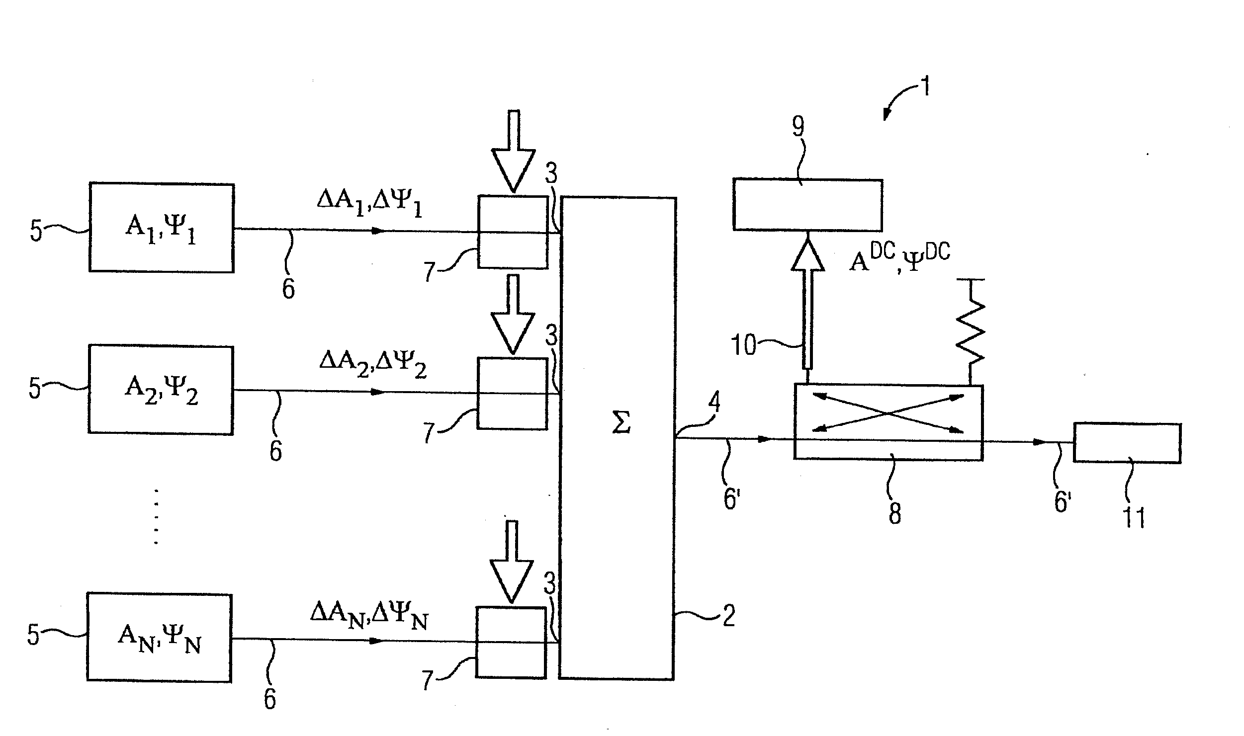
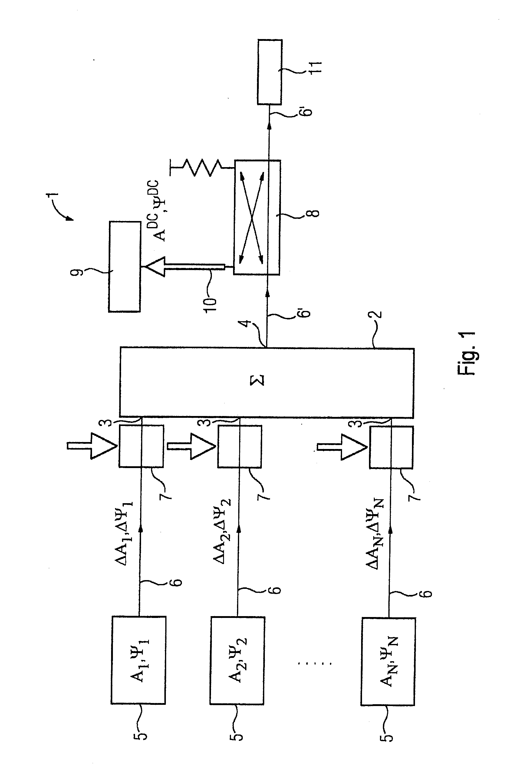
[0028]FIG. 1 shows an arrangement 1 for RF high power generation in accordance with the present invention, comprising a power combiner 2 having RF inputs 3 and an RF output 4. Power amplifier modules 5 with their output are electrically connected respectively by a transmission line 6 to the respective input 3 of the power combiner 2. An RF switch 7 comprises every transmission line 6, arranged in-between the output of the respective RF module and the respective input 3 to the power combiner 2. A directional coupler 8 is electrically connected to the RF output 4 of the power combiner 2, in-between the output 4 and a load 11, within an output transmission line 6′. An amplitude ADC and phase ΨDC detector is electrically connected to the directional coupler 8, in the forward signal direction 10.

[0029]With a number N of RF module power amplifiers 5, as depicted in FIG. 1 by doted points between the second and the number N module 5, a number of N inputs 3 of the power combiner 2 are respe...


PUM


Abstract

A method and arrangement for RF high power generation includes a power combiner having RF inputs and an RF output, and at least two power amplifier modules, respectively electrically connected by a transmission line to an input of the power combiner, wherein a directional coupler is electrically connected to the RF output of the power combiner and every transmission line includes an RF switch, where the Method includes measuring and determining values of the power amplifier modules, storing the values and applying the values as a correction to the input signal of the power amplifier modules.

Description

CROSS-REFERENCE TO RELATED APPLICATIONS[0001]This is a U.S. national stage of application No. PCT / RU2013 / 001164 filed 24 Dec. 2013.BACKGROUND OF THE INVENTION[0002]1. Field of the Invention[0003]The present invention relates to a method and arrangement for Radio-Frequency (RF) high power generation comprising at least one power combiner having RF inputs and at least one RF output, and at least two power amplifier modules, which are respectively electrically connected by at least one transmission line to an input of the at least one power combiner.[0004]2. Description of the Related Art[0005]Radio-Frequency Radio-Frequency (RF) and / or microwave power is produced with appropriate generators. RF power generators for high power applications are based on tubes, such as klystrons, inductive output tubes or magnetrons. Alternatively, solid state technology is used for RF power generators, particularly transistor technology. With solid state RF power generators, a reliable RF power producti...

Claims


Application Information

Patent Timeline
Patent Type & Authority Applications(United States)
IPC IPC(8): H03F3/60H03F3/21H03F3/72H03F3/19
CPCH03F3/602H03F3/19H03F3/21H03F2200/451H03F2203/7236H03F2200/102H03F3/72H03F2200/421H03F2203/211H03F3/20H03F3/60H03F3/68
Inventor IVANOV, EVGENYKRASNOV, ANDREYNIKOLSKIY, KONSTANTINPOLIKHOV, STEPANSHARKOV, GEORGYSMIRNOV, ALEXANDER
Owner OOO SIEMENS
Why Eureka
Try Eureka