
Nucleus pulposus trial device and technique

a trial device and nucleus pulposus technology, applied in the field of nucleus pulposus trial device and technique, can solve the problems of high toxicity, retard the flow of nutrients into the disc, and the accumulation of toxins, so as to improve the determination of implant sizing and placement, improve the safety and effectiveness of procedures, and improve the effect of implant performan

Active Publication Date: 2010-04-20
DEPUY SPINE INC (US)
View PDF21 Cites 25 Cited by
  • Summary
  • Abstract
  • Description
  • Claims
  • Application Information

AI Technical Summary

Benefits of technology

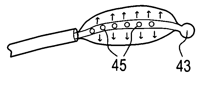
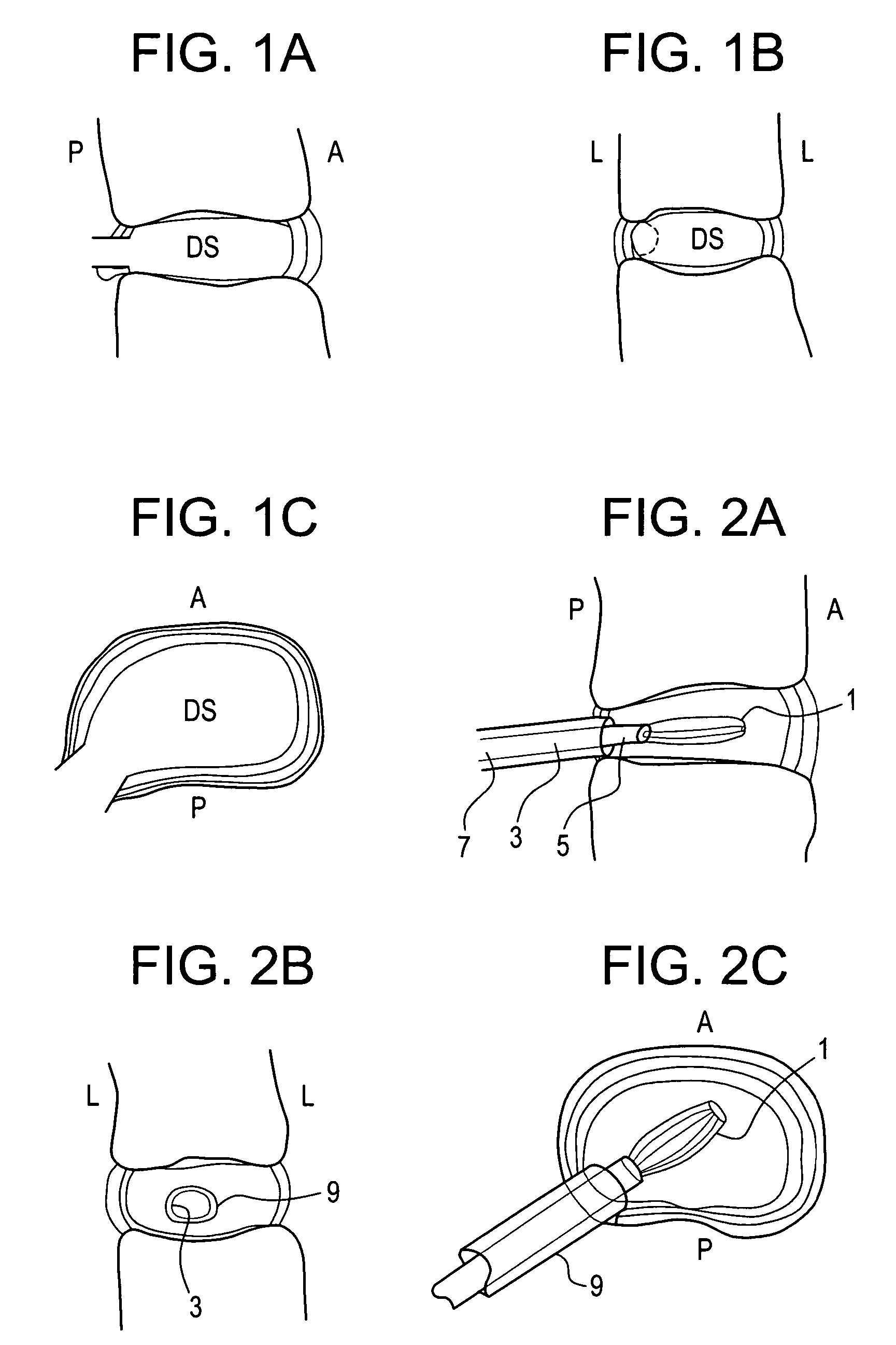
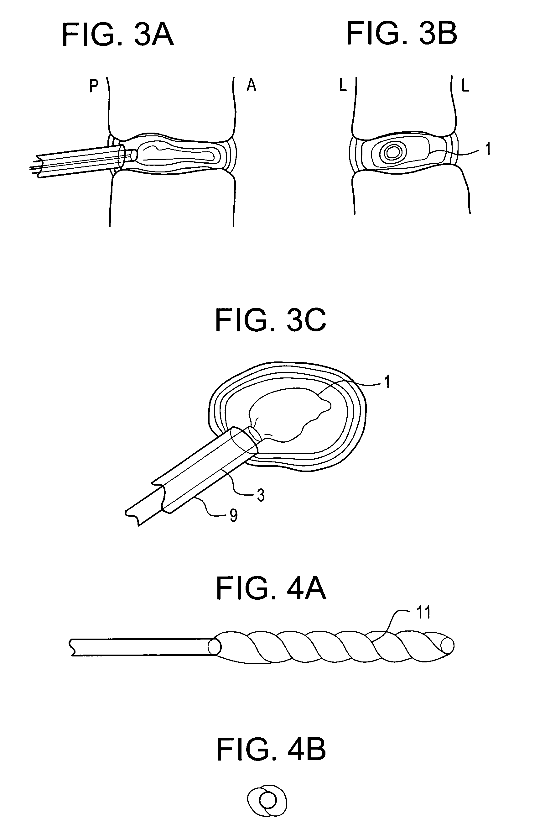
[0013]It is an object of the present invention to provide an inflatable, intra-operative trial device and a method to determine, the size, location and geometry of an intradiscal space following discectomy. The invention improves the determination of implant sizing and placement, as well as implant performance, thereby leading to improved procedure safety and effectiveness.
[0015]In accordance with the present invention, a discectomy is first performed upon a patient having a degenerated disc to produce a disc space. Next, a balloon is inserted into the disc space through a hole in the annulus fibrosus, and inflated to conform to the size and shape of the cleared disc space. In order to visualize the shape of the balloon, the balloon is comprised of, or is inflated with, a radiographic material. Next, an imaging technique is used to visualize the inflated trial balloon and hence determine the size, location and geometry of the cleared disc space. This enables the surgeon to determine the suitable location and size of the implant and to verify that the site has been adequately prepared.

Problems solved by technology

In other instances of DDD, genetic factors, such as programmed cell death, or apoptosis can also cause the cells within the nucleus pulposus to emit toxic amounts of these cytokines and MMPs.
In some instances, the pumping action of the disc may malfunction (due to, for example, a decrease in the proteoglycan concentration within the nucleus pulposus), thereby retarding the flow of nutrients into the disc as well as the flow of waste products out of the disc.
This reduced capacity to eliminate waste may result in the accumulation of high levels of toxins.
As DDD progresses, the toxic levels of the cytokines present in the nucleus pulposus begin to degrade the extracellular matrix (in particular, the MMPs (under mediation by the cytokines) begin cleaving the water-retaining portions of the proteoglycans, thereby reducing its water-retaining capabilities).
This degradation leads to a less flexible nucleus pulposus, and so changes the load pattern within the disc, thereby possibly causing delamination of the annulus fibrosus.
These changes cause more mechanical instability, thereby causing the cells to emit even more cytokines, thereby upregulating MMPs.
As this destructive cascade continues and DDD further progresses, the disc begins to bulge (“a herniated disc”), and then ultimately ruptures, causing the nucleus pulposus to contact the spinal cord and produce pain.
Intervertebral disc degeneration causes a number of clinical problems, including sequelae related to reduced disc height and herniation.
In many cases, a simple discectomy can effectively relieve pain, but in time results in further collapse of the disc space because the intervertebral disc can no longer resist body loads the same as a healthy disc.
The ability of a surgeon to accurately determine the position, size and shape of the cleared disc space during discectomy is currently limited by many factors, including the procedure approach, access, location and the size through the annular wall, as well as available intraoperative imaging techniques.
Improper location, size or shape of the cleared disc space following discectomy can greatly impact the size, placement and securement of intervertebral devices that are ultimately placed in the disc space, as well as the biomechanical loading of the device and the physiologic response to the device.
For example, improper lateral placement of a nucleus pulposus replacement device may cause migration or expulsion of this implant, leading to continued height loss and irritation of neighboring tissues (including nerve roots), thereby creating additional pain or requiring re-operation.
Felt does not disclose the use of a radiographic disc space trial balloon that is inflated to verify the size and geometry of the disc space.

Method used


Image

  • Nucleus pulposus trial device and technique
  • Nucleus pulposus trial device and technique
  • Nucleus pulposus trial device and technique

Examples


example

[0113]In performing a preferred prophetic method of the present invention, the patient is brought to the pre-surgical area and prepped. Anesthesia is then induced and the area of the spine is further prepped. A small incision through the muscles is opened under dissecting microscopic visualization. The incision is made as small as possible and is longitudinal in the plane of the spine. The paravertebral muscles are separated by blunt dissection and held apart with forceps and dividers. The intervertebral disc area is visualized, with initial exposure down to the lamina. The area below the lamina, at the point of the intervertebral foramina, can also be exposed.

[0114]The disc is examined for extruded material and any extruded material is removed. Magnetic resonance imaging (“MRI”) data can be used to determine the integrity of the annulus fibrosis at this point. An arthroscope is inserted into the disc and used to examine the inside of the annulus. Optionally, an intraoperative disco...


PUM

PropertyMeasurementUnit
angleaaaaaaaaaa
angleaaaaaaaaaa
angleaaaaaaaaaa

Abstract

A nucleus pulposus trial device for assessing the size, shape and location of a disc space.

Description

BACKGROUND OF THE INVENTION[0001]The natural intervertebral disc contains a jelly-like nucleus pulposus surrounded by a fibrous annulus fibrosus. Under an axial load, the nucleus pulposus compresses and radially transfers that load to the annulus fibrosus. The laminated nature of the annulus fibrosus provides it with a high tensile strength and so allows it to expand radially in response to this transferred load.[0002]In a healthy intervertebral disc, cells within the nucleus pulposus produce an extracellular matrix (ECM) containing a high percentage of proteoglycans. These proteoglycans contained sulfated functional groups that retain water, thereby providing the nucleus pulposus within its cushioning qualities. These nucleus pulposus cells may also secrete small amounts of cytokines as well as matrix metalloproteinases (“MMPs”). These cytokines and MMPs help regulate the metabolism of the nucleus pulposus cells.[0003]In some instances of disc degeneration disease (DDD), gradual de...

Claims


Application Information

Patent Timeline
Patent Type & Authority Patents(United States)
IPC IPC(8): A61F2/44
CPCA61F2/4657A61F2/4684A61B2017/0256A61F2250/0098A61F2002/3008A61F2002/30556A61F2002/30581A61F2002/30584A61F2002/30586A61F2002/30588A61F2002/444A61F2002/4495A61F2002/4663A61F2250/0009A61F2/441
Inventor O'NEIL, MICHAELSERHAN, HASSANDOORIS, ANDREW
Owner DEPUY SPINE INC (US)
Learn More