Electronically agile multi-beam antenna

a multi-beam antenna, electromagnetic technology, applied in the direction of antennas, antenna adaptation in movable bodies, instruments, etc., can solve the problems of increasing the difficulty of radar antenna system technology to provide sufficient information, the current radar antenna system is generally proving inadequate in terms of detection range, field of view, resolution, or combinations, and the radar antenna system may not be able to provide information on the other aircraft in time to avoid a collision

Inactive Publication Date: 2004-08-03
BALL AEROSPACE & TECHNOLOGIES
View PDF32 Cites 46 Cited by
  • Summary
  • Abstract
  • Description
  • Claims
  • Application Information

AI Technical Summary

Benefits of technology

A further object of the present invention is to provide an antenna system that can be used in high-speed, high-temperature environments which substantially reduces the need for a radome formed of exotic material and / or the use of a complex cooling system.
In yet another embodiment, the beamformer includes multiple channels so that multiple beams can be formed simultaneously and thereby expedite the determination of unknown parameter values associated with the object relative to a beamformer with one or fewer channels.

Problems solved by technology

Present radar antenna system technology is becoming increasingly hard-pressed to provide sufficient information on the space around an aircraft as the speed of the aircraft on which the radar antenna system is mounted and of the other aircraft in the surrounding airspace increases.
Specifically, present radar antenna systems are generally proving inadequate with respect to their detection range, field of view, resolution, or combinations thereof in situations that involve high-speed aircraft.
For example, if the radar antenna system in one of two high-speed aircraft that are approaching one another has a short range, the radar antenna system may not be able to provide information on the other aircraft in time to avoid a collision.
If, on the other hand, the radar antenna system in an aircraft has a limited area of coverage, and the aircraft is attempting to join up with a high-speed aircraft, the high-speed aircraft may not be detected with such a radar antenna system.
Further, if the antenna system in an aircraft has a limited resolution, the ability of the aircraft to make the appropriate course corrections may be compromised.
These temperatures present severe radiation problems to any radar antenna system mounted on the aircraft.
However, the ability to realize the improved performance is becoming increasing sensitive to anything that may affect the aerodynamics of the aircraft.
The ability of aircraft-based radar antenna systems to provide adequate information on objects in the surrounding space is also becoming increasingly difficult due to the reductions in the radar cross-sections of many of these objects.
For example, as aircraft become more aerodynamic, their radar cross-section typically decreases, thereby making it more difficult for a radar antenna system to detect the aircraft.
At least with respect to aircraft-based radar, the space to accommodate additional sensors, and especially those sensors that are to be used in high-speed aircraft environments, is limited.
Another application in which the performance of present antenna systems is becoming increasingly less reliable is when there is a need for a very focused or narrow beam (transmitted or received) with low side lobes and / or high gain.
Present antenna systems that use partially overlapping beams in such situations have become increasingly less reliable as the need to operate in lower SNR environments increases.
Yet a further concern with respect to antenna systems is that as the performance requirements of the various applications has increased, the antenna systems that are designed to meet these requirements have tended to become more complex.
This is of concern because increasing complexity generally results in a reduced reliability that is unacceptable in many applications.
Further, even though such an antenna system may be relatively inexpensive, the cost of the system is probably still greater than is necessary.

Method used


Image

  • Electronically agile multi-beam antenna
  • Electronically agile multi-beam antenna
  • Electronically agile multi-beam antenna

Examples


first embodiment

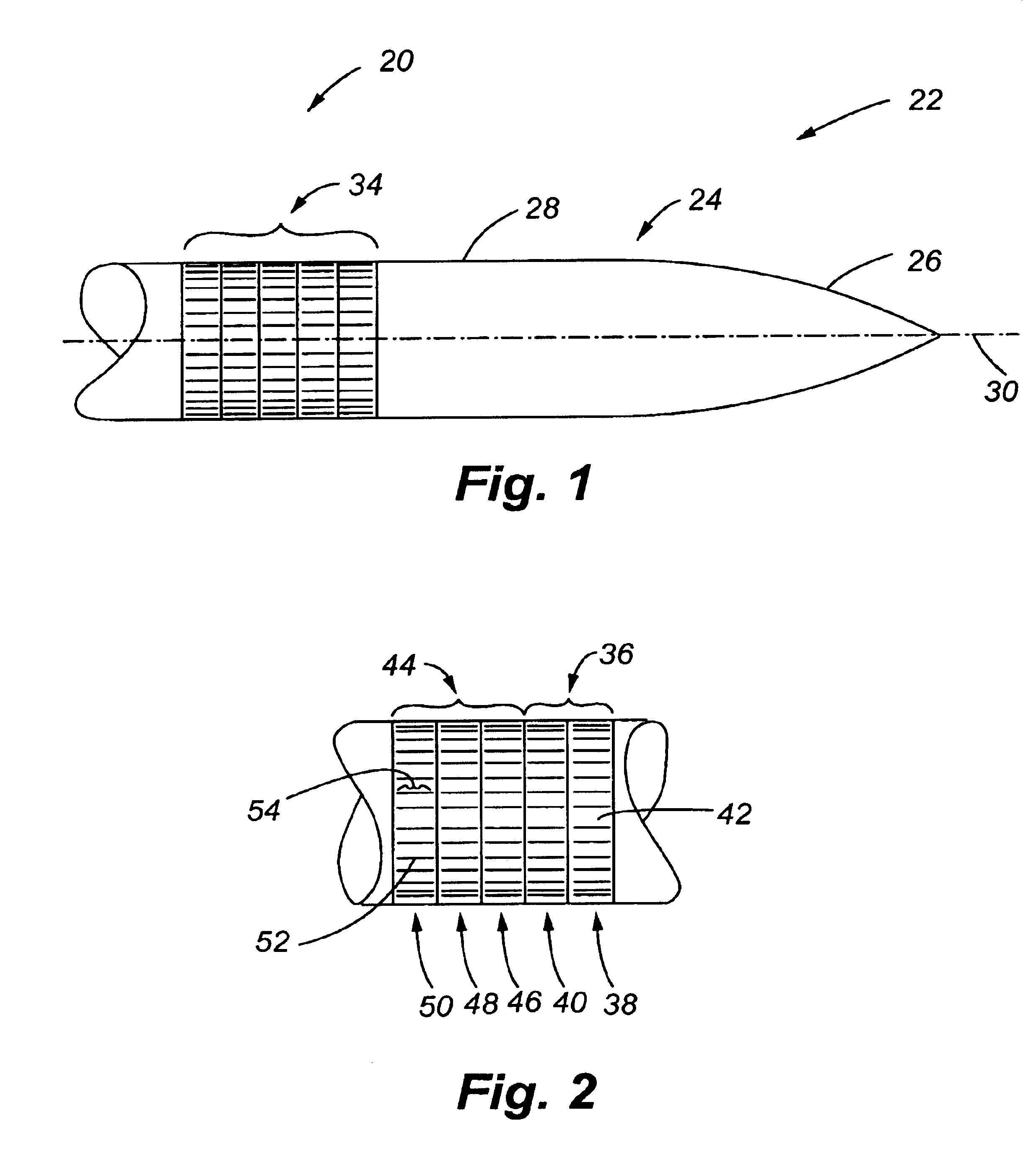
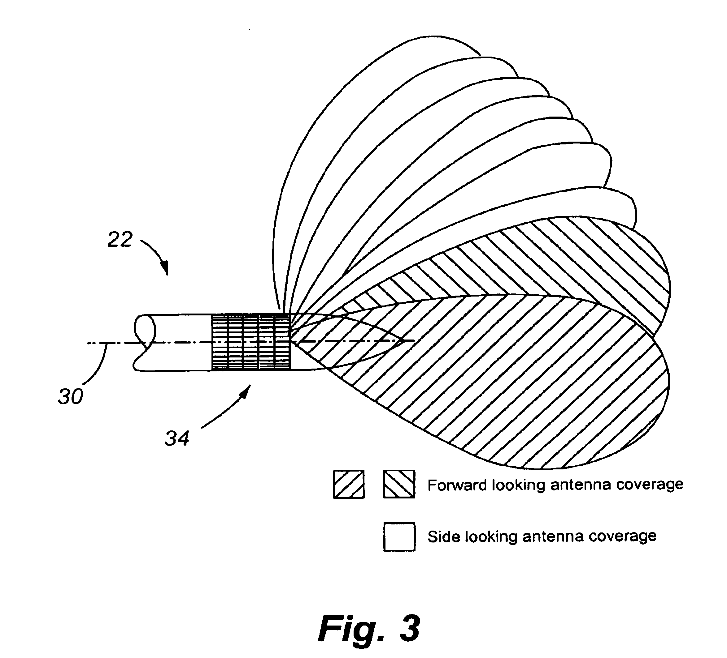
FIG. 1 illustrates the antenna system of the present invention 20, hereinafter referred to as antenna system 20. The antenna system 20 is part of a radar that is located on an aircraft 22 which has an exterior surface 24 comprised of a front or nose surface 26, a cylindrical side surface 28, and a longitudinal axis 30 that also defines the direction of movement of the aircraft 22. To distinguish the nose surface 26 from the side surface 28, any point on the nose surface 26 has a surface area vector that is other than perpendicular to the longitudinal axis 30 and any point on the side surface has an area vector that is substantially perpendicular to the longitudinal axis 30.

The antenna system 20 includes an antenna array 34 that is mounted on the side surface 28 of the aircraft 22 such that it has a low profile with respect to the side surface 28. In this case, the antenna array is substantially conformal with the side surface 28. The low-profile or conformal mounting of the antenna ...

second embodiment

With reference to FIG. 11, the antenna system 20 is illustrated. This embodiment of the antenna system 20 is useful in reducing the possibility of the signals that are being transmitted or received by the antenna system being intercepted and is also capable of being used in low SNR environments. The antenna system 20 includes a surface 150 that is comprised of eight facets 152 that each support a portion of the antenna array. More specifically, each facet 152 supports two column arrays 154 that are separated from one another. Each of the column arrays 154 is comprised of a plurality of vertically juxtaposed subarrays 156. Each subarray 156 is, in turn, comprised of four horizontally juxtaposed antenna elements 158. The antenna element 158 is a nine dipole asymmetric log periodic antenna element. The spacing between the antenna elements 158 comprising the subarray 156 is tapered in depth so that a frequency-independent azimuth beamwidth is realized across the frequency bandwidth of t...

third embodiment

FIG. 16 illustrates the antenna system 20. The antenna system 20 is part of a radar that is located on an aircraft 202 which has an exterior surface 204 comprised of a front or nose surface 206, a cylindrical side surface 208, and a longitudinal axis 210 that also defines the direction of movement of the aircraft 202. To distinguish the nose surface 206 from the cylindrical side surface 208, any point on the nose surface 206 has a surface area vector that is other than perpendicular to the longitudinal axis 210 and any point on the side surface has a surface area vector that is substantially perpendicular to the longitudinal axis 210.

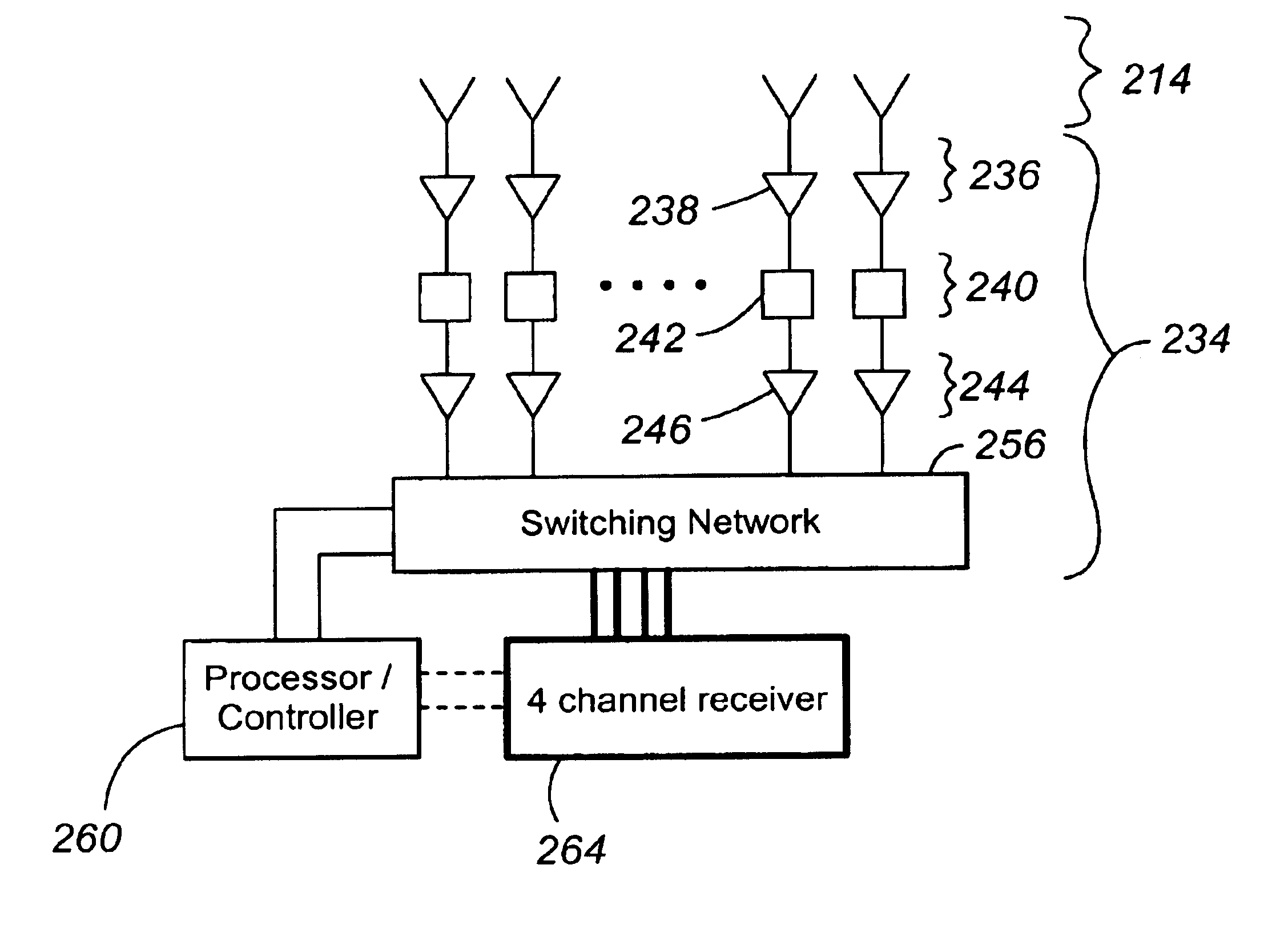
The antenna system 20 includes a forward-looking receive array 214 for receiving electromagnetic signals from a source in a defined field of view (FOV) and converting these electromagnetic signals into electrical signals from which beams can be formed that can be used to determine information on the source of the electromagnetic radiation, which is here...


PUM


Abstract

The present invention provides an antenna system including a body for use in determining N unknown parameters values relating to an object located in the vicinity of the system. The system further includes an antenna array comprised of a plurality of elements that are spaced to reduce ambiguities in the subsequently determined N values. In one embodiment, several pair of elements are used. The spacing between the elements comprise the pairs and the spacing between pairs reduces ambiguities. The antenna system also includes a beamformer for producing a plurality of beams and a device for using the plurality of beams to determine N values associated with the object. The amplitude of the plurality of beams can be compared to obtain coarse data on the object. The phases of the plurality of spatially independent but overlapping beams are compared to realize an interferometer that can provide coarse resolution data and / or fine resolution data on the position and / or polarization of an object relative to the antenna system. The amplitudes of the beams can also be compared to obtain coarse data on the position and / or polarization of the object. The beamformer includes a switching network for selecting which elements of the antenna array form the subsets. This permits, for example, the position of the beams to be moved and the baseline of the beams to be varied.

Description

1. Field of the InventionThe present invention relates to antenna systems and, in particular, to an antenna system that uses a multi-element antenna array to receive an electromagnetic signal and generate a plurality of electrical signals that are representative of the received electromagnetic signal and a multi-beam beamformer to produce at least two spatially independent, overlapping beams from the electrical signals provided by the array.2. Description of the Related ArtPresently, antenna systems are used in many aeronautical applications. One application for an antenna system is as part of a radar on an aircraft where the antenna system is used to obtain positional information on the objects in the space surrounding the aircraft. This positional information is then typically used to either avoid an object, such as another aircraft, or to home in on an object, such as a navigational beacon.Present radar antenna system technology is becoming increasingly hard-pressed to provide su...

Claims


Application Information

Patent Timeline
Patent Type & Authority Patents(United States)
IPC IPC(8): H01Q3/22H01Q3/26G01S13/48G01S13/66H01Q1/28H01Q3/24H01Q21/20H01Q25/02
CPCG01S13/48H01Q1/28H01Q3/24H01Q21/205H01Q25/02
Inventor LALEZARI, FARZINBOONE, THERESA CRONIN
Owner BALL AEROSPACE & TECHNOLOGIES
Why Eureka
Try Eureka