
Wireless communications in a multi-sector network

a multi-sector network and wireless communication technology, applied in the field of wireless communication in a multi-sector network, can solve the problems of delay in transmission, limited improvement in throughput, and several drawbacks in the method

Active Publication Date: 2010-04-27
SPARKMOTION
View PDF5 Cites 20 Cited by
  • Summary
  • Abstract
  • Description
  • Claims
  • Application Information

AI Technical Summary

Benefits of technology

[0007]It is an object of the present invention to provide a method and apparatus that allow achieving higher spectral efficiency without having an adverse effect upon the peak rate.
[0009]It is another object of the present invention to provide a method and device that are adapted to allow transmission of a plurality of maps while using system resources required for the transmission of a lower number of maps (e.g. one map), so as to reduce the high map overheads used in different standards such as the WiMax.
[0010]It is yet another object of the present invention to provide a method and device to provide the above advantages while adding a low cost hardware to the already existing hardware in the base station.
[0011]It is still another object of the present invention to allow deploying two or three sectors with the resources typically required for a single AAS sector, thus achieving higher spectral efficiency than an AAS sector, without significantly increasing sector cost.
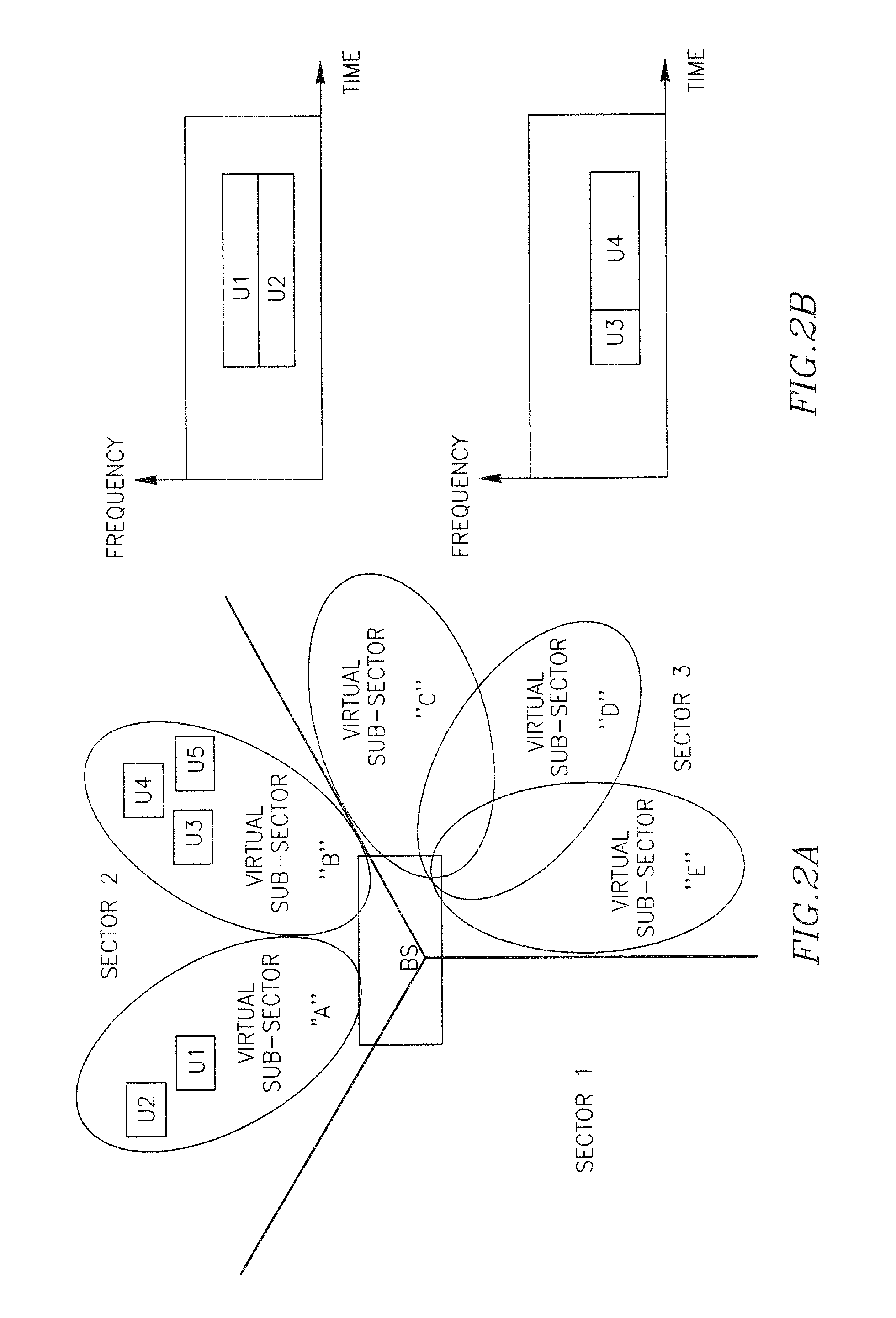
[0024]The maps referred to herein, for different virtual sub-sectors can preferably be orthogonal maps (between virtual sub-sectors), and operate in a mode of reuse-1 vs. other sectors, thereby reducing MAP interference between the virtual sub-sectors significantly.
[0036]By yet another aspect of the present invention there is provided a communication device adapted to be used in an SDMA wireless system, and operative to divide one or more sectors comprised in the wireless communications network into a plurality of virtual sub-sectors, to select at least one pair of subscriber devices, both having array signatures that are substantially orthogonal to each other from among the plurality of the virtual sub-sectors, to generate and transmit frequency-time allocations maps based on the selection of the matched pair(s) to each of the sub-sectors, and to schedule the transmission destined to each of the subscriber devices associated therewith so as to maximize the SDMA gain.

Problems solved by technology

Therefore, the additional power increase achievable by adaptive antenna system yields limited improvement in terms of throughput.
Furthermore, one other problem characterizing this kind of a solution is the inherent delay associated with the transmissions, because as was explained above, transmissions are exchanged only when there is a peak in the channel power.
Still, this method also suffers from several drawbacks.
One of these drawbacks is related to the transmission of a control channel by the base station and its reception by the subscriber stations.
The information contained in the map is required for a number of reasons, for example a subscriber that tries to demodulate a time and frequency allocation beamformed to another user, will typically fail.
Moreover, the map cannot be beamformed since all subscribers need to be able to read it.
In other words, currently there is no way to beamform or spatial multiplex the maps to allow improving the spectral efficiency of the maps.
However as we add more sectors, some sectors are likely to have little or no traffic, so that in this case spectral efficiency gain would not be achieved in a practical setting.
In addition this solution does not increase the peak rate of a user or the peak throughput of a sector, in contrast these two parameters are lower as interference from other sectors is increased.

Method used


Image

  • Wireless communications in a multi-sector network
  • Wireless communications in a multi-sector network
  • Wireless communications in a multi-sector network

Examples


Embodiment Construction

[0043]A better understanding of the present invention is obtained when the following non-limiting detailed description is considered in conjunction with the following drawings in which:

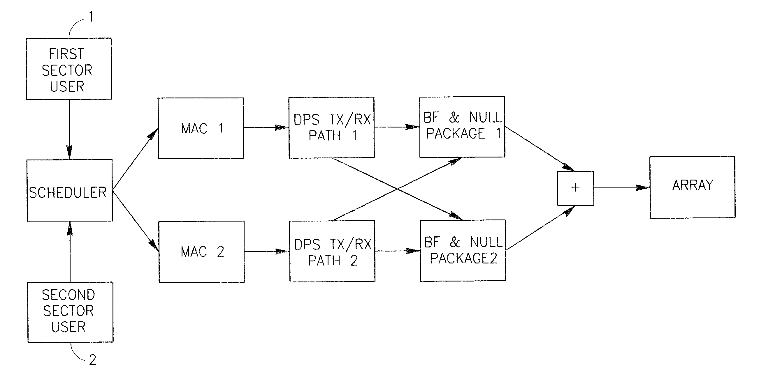
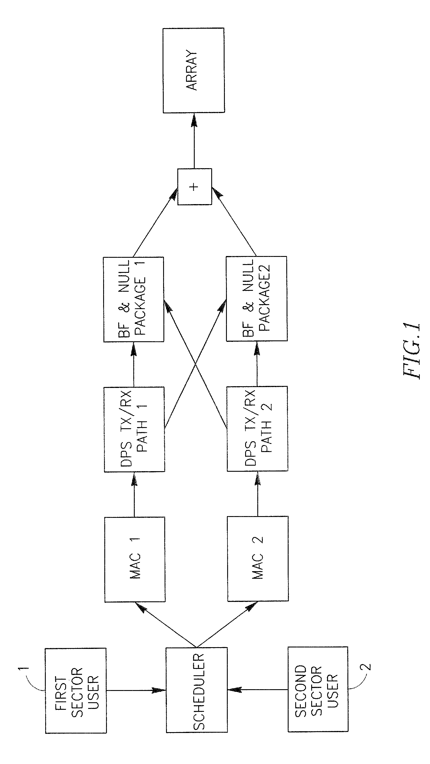
[0044]FIG. 1 describes an example of an embodiment of the present invention for using the resources of a single physical sector (i.e. a single antenna array) to generate two (Nsec=2) virtual sub-sectors. For WiMax typically the number of virtual sub-sectors is Nsec<=3.

[0045]Each path in FIG. 1 illustrates one virtual sub-sector. For example let us assume that user 1 is scheduled on virtual sub-sector 1, and is therefore handled by path 1, while user 2 is scheduled on virtual sub-sector 2 and is handled by path 2. The scheduler, which is shared by the two virtual sub-sectors, generates two users allocations maps (one for each virtual sub-sector), which are then processed by the MAC entities (MAC1 and MAC2). The scheduler needs to schedule transmissions to / from pairs of users (say user 1 and user 2) whi...


PUM


Abstract

In a wireless network employing Spatial Division Multiplexing Access (“SDMA”) in at least one of its cells, a method is provided for dynamically allocating transmission resources to different subscriber devices. The method comprises the steps of: providing at least one base station comprising at least one antenna array; providing one or more sectors associated with that wireless communications network; dynamically dividing one or more of the sectors into a plurality of virtual sub-sectors, each allowing communications between the base station and at least one respective subscriber; from among the plurality of the virtual sub-sectors, selecting at least one pair of subscriber devices wherein each of the pair of subscriber devices is not interfered substantially by transmissions directed to the other subscriber of that pair; for each of the divided sectors, generating plurality of time frequency allocation maps; transmitting the generated maps to all virtual sub-sectors associated with the respective sector; and for each of the sectors, beamforming the transmissions to be conveyed to the subscriber devices' pairs, summing them and conveying the summed result towards the array antenna.

Description

FIELD OF THE INVENTION[0001]The present invention relates to method and apparatus adapted to improve the transmission of uplink and downlink signals and broadcast control signals in wireless communications systems, and more particularly to the improvement in Spatial Division Multiplexing Access (“SDMA”) type of wireless networks.BACKGROUND OF THE INVENTION[0002]In a base station having an adaptive antenna array, when a subscriber device is due to exchange communications with its base station, a beam from the base station is directed towards that subscriber device (referred to herein as “beamforming”), and the received power for that subscriber device is respectively increased, roughly by 10*log 10 (Number of Antennas) relative a non beam formed case. Modern cellular wireless systems typical employ multi-user scheduling in order to improve the overall system throughput. This is done by scheduling transmissions to / from a given user when its channel power peaks, while scheduling-transm...

Claims


Application Information

Patent Timeline
Patent Type & Authority Patents(United States)
IPC IPC(8): H04W4/00H04W16/28H04W72/08H04W72/12
CPCH04W72/046H04W16/28H04W72/082H04W72/541
Inventor STOPLER, DANROTH, ZE'EVCHAYAT, NAFTALI
Owner SPARKMOTION
Learn More