Actuator for use in fenestration systems

a technology for fenestration systems and actuators, applied in mechanical controls, carpet fasteners, mechanical apparatuses, etc., can solve problems such as the possibility of prying into the edge of the frame, and achieve the effects of less expensive, simple manufacturing and operation, and simple construction

Active Publication Date: 2010-05-04
CALDWELL MFG NORTH AMERICA
View PDF25 Cites 30 Cited by
  • Summary
  • Abstract
  • Description
  • Claims
  • Application Information

AI Technical Summary

Benefits of technology

[0008]Our first improvement is the use of a uniformly flexible push-pull member that can be used not only to transfer movement around a fenestration corner, but to transfer movement all the way from a distant location on the fenestration edge to a locking member. Thus, our flexible push-pull member can be used to transfer movement from a locking lever at the bottom of a window around the corner and up the side of the frame (or “jamb”) to the position of the upper-most locking pin. In addition, the location of the operative parts of our invention can be reversed. For example, the flexible push-pull member and related parts can be mounted on the door or sash with keepers mounted on or incorporated into the doorframe or jamb. The actuating assembly can, likewise, be mounted either with the flexible push-pull member or opposed to it. Thus, for example, it can be mounted with the flexible push-pull member on a sash or opposed to it on a frame. Further, our invention, unlike prior art devices, is capable of use around irregularly shaped windows and doors. Thus, it can easily be adapted for use around a round window or window opening.
[0009]In our invention, locking pins are not directly attached to the flexible member. In some embodiments of our invention, the locking pins have collars or enlarged portions that trap the pins in place under slotted guides mounted on the edges of the fenestration or fenestration closure means. In other embodiments, the guide is a slotted cover strip that overlays the flexible member and locking pins. In either case, the locking pin is generally provided with a coaxial motion transmitting pin or member that extends into regularly spaced perforations in the flexible member. This eliminates any permanent connection between our locking pins and the flexible member and simplifies the installation of the pins and flexible member. It also allows the locking pins to be mounted to engage various perforations in the flexible member, depending on the dimensional requirements of the door, window, or opening in question. Finally, it can be used to easily increase the locking points for a given sized window. This makes the window more secure and also allows it to pass higher test standards.
[0010]We have also improved the actuating assembly used in our invention. It has a simple three-piece structure. In general, it features a lower piece with a slot that runs parallel with and above the flexible member (or “locking tape”), and an upper piece with a slot oriented transverse to the direction of movement of the locking tape. In this configuration, the locking lever has a drive pin that extends into the locking tape and a pivot pin that extends upward into the slot running transverse to the tape. However, our actuating assembly can also be constructed with both slots and both pins on the same side of the locking lever. In either configuration, as the lever is rotated, the pivot pin moves along the length of the transverse slot while the tape drive pin drives along the direction of movement of the tape. This, in effect, creates a lever arm that is rotatable about two axes of rotation, one provided by the drive pin and the other provided by the pivot arm. The arrangement provides a low mechanical advantage and higher speed movement as the locking motion is commenced, and a greatly increased mechanical advantage and slower speed movement as the locking pins are driven home to pull the sash or door snuggly into a sealed closure with its frame. The arrangement also aligns the two pins with the direction of movement of the tape. Thus, when the sash or door is locked, it is not possible to pry into the edge of the frame and push against the locking pins to move the tape to an unlocked position.
[0011]These improvements serve to create a fenestration locking system that is similar in function but simpler and more effective in installation and application than prior art devices. Indeed, all a user generally needs for implementing our invention in a window or door opening is (1) a strip of flexible member; (2) one or more of our pins; (3) pin guides; (4) a corner bracket for guiding the flexible member around sharp corners; (5) keepers for placement on frame, door, or sash; and (6) an actuating assembly. There is no further need for fixed length locking bars with pins mounted on the locking bars in addition to guide plates supporting such pins or locking bars. These improvements also serve to create a single lever locking system that is significantly less expensive. Indeed, our improved actuating assembly is so compact that the locking lever can fit directly below the operator that opens and closes a sash, putting all the controls neatly in a single location and avoiding any interference with window blinds and curtains. These and the numerous other advantages of our invention will become evident upon review of the drawings and detailed description that follow.

Problems solved by technology

Thus, when the sash or door is locked, it is not possible to pry into the edge of the frame and push against the locking pins to move the tape to an unlocked position.

Method used


Image

  • Actuator for use in fenestration systems
  • Actuator for use in fenestration systems
  • Actuator for use in fenestration systems

Examples


Embodiment Construction

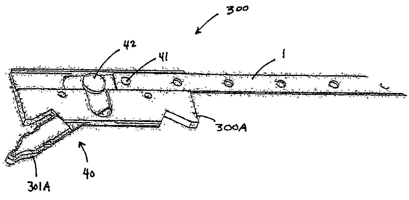
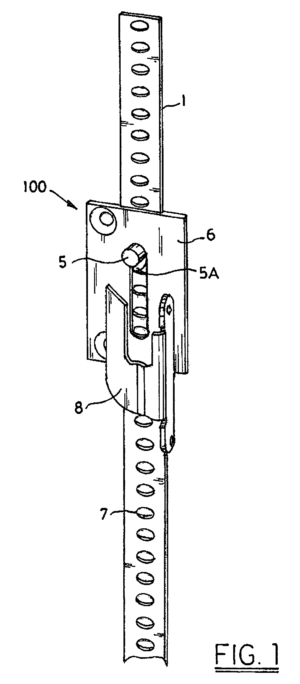
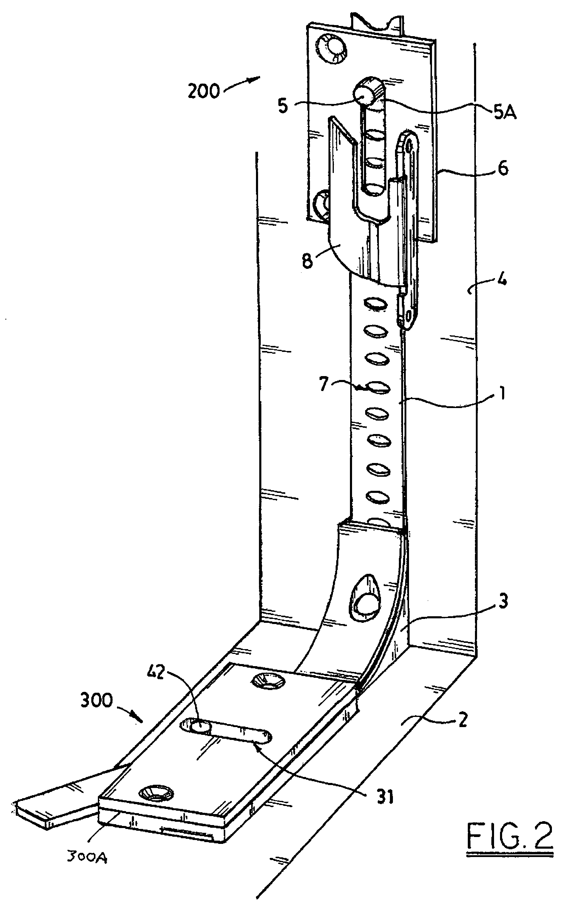
[0057]Tape 1 serves as the flexible push-pull member in our design and can start at an actuating assembly (denoted generally by arrow 300). In the embodiments of our invention illustrated in FIGS. 1 through 4B, actuating assembly 300 is mounted on a windowsill 2 or at other locations on the frame (or perimeter) of a fenestration opening. Tape 1 can extend to as many locking pin assembly locations as desired. These could be placed all the way around the perimeter of a fenestration opening (e.g.-all the way around a window or doorframe). In most cases, however, a swinging sash or door will require only the installation of an upper locking pin assembly (denoted generally by arrow 100) and a lower locking pin assembly (denoted generally by arrow 200) on frame 4 in order to ensure that the sash or door is securely fastened when closed. Thus, in the preferred embodiments illustrated in FIGS. 1 through 3, tape 1 extends around the corner of a window frame via corner bracket 3 and upward al...


PUM


Abstract

An actuator for use in fenestration systems having a swinging sash or door is characterized by the use of a linear member running continuously from an actuating assembly to a locking pin assembly. The linear member can be a flexible linear member, allowing it to convey motion to the locking pin assembly around corners. The locking pin assembly has a moveable locking pin with an actuator and an extension that can engage a keeper. The linear member has multiple actuator engagement sites along its length where the actuator of the locking pin can engage the linear member. The linear member can then be used to move the locking pin with respect to the locking pin assembly so that the extension can engage or disengage a keeper. The locking pin assembly can be mounted on a fenestration frame and the keeper opposingly mounted on a window or door mounted in the fenestration frame. Alternately, the keeper can be incorporated into the fenestration frame and the locking pin assembly opposingly mounted on the window or door mounted in the fenestration frame.

Description

RELATED APPLICATIONS[0001]This application is a Continuation-In-Part of copending parent application Ser. No. 10 / 154,246, filed 23 May 2002, entitled FENESTRATION LOCKING SYSTEM, which parent application claims the benefit of U.S. Provisional Application No. 60 / 294,533, filed on 30 May 2001. Both the parent application and the Provisional application are hereby incorporated by reference.TECHNICAL FIELD[0002]This invention deals generally with actuators for use in fenestration systems for openings having a swinging closure means such as a swinging sash, door, or gate. More specifically, it pertains to locking systems that use sliding elements to transfer locking motion, especially those using bendable sliding elements to transfer locking motion around a corner. It emphasizes systems using a flexible push-pull member and actuating lever handle arrangements suitable for use with such systems.BACKGROUND OF THE INVENTION[0003]Fenestration is generally considered to include any opening in...

Claims


Application Information

Patent Timeline
Patent Type & Authority Patents(United States)
IPC IPC(8): E05C1/02E05C1/00E05B53/00E05C9/00E05C9/02E05C9/06E05C9/18
CPCE05C9/063E05C9/185E05C9/14E05C9/025E05C9/24E05C9/22E05B53/003Y10S292/20Y10S292/47Y10T292/0841Y10T292/57Y10T292/1017Y10T292/0839Y10T292/096
Inventor TIMOTHY, E. ERIKMINTER, PETER
Owner CALDWELL MFG NORTH AMERICA
Why Eureka
Try Eureka