
Splice bar for connecting cable tray sections

a technology of splice bar and cable tray, which is applied in the direction of rod connection, building components, building scaffolds, etc., can solve the problem of not being able to adapt to the bottom of the cable tray, and achieve the effect of increasing the stiffness of the splice bar

Inactive Publication Date: 2010-05-04
I C M GRP
View PDF12 Cites 18 Cited by
  • Summary
  • Abstract
  • Description
  • Claims
  • Application Information

AI Technical Summary

Benefits of technology

[0017]To increase the stiffness of the splice bar, in particular when fitting or removing it, for a given thickness of plate, the central part advantageously includes stiffener bosses.

Problems solved by technology

They are not adapted to be used for the bottom of a cable tray.

Method used


Image

  • Splice bar for connecting cable tray sections
  • Splice bar for connecting cable tray sections
  • Splice bar for connecting cable tray sections

Examples


Embodiment Construction

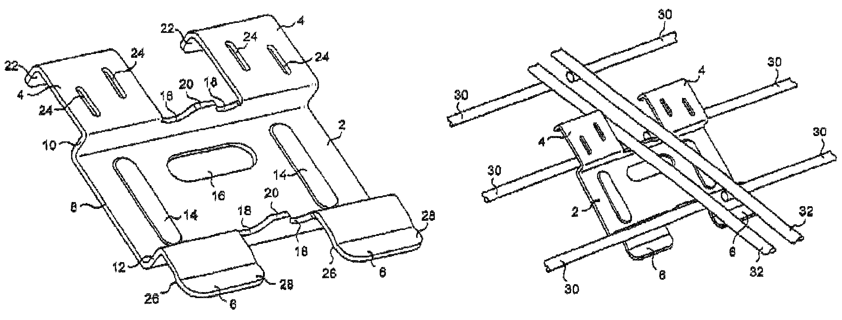
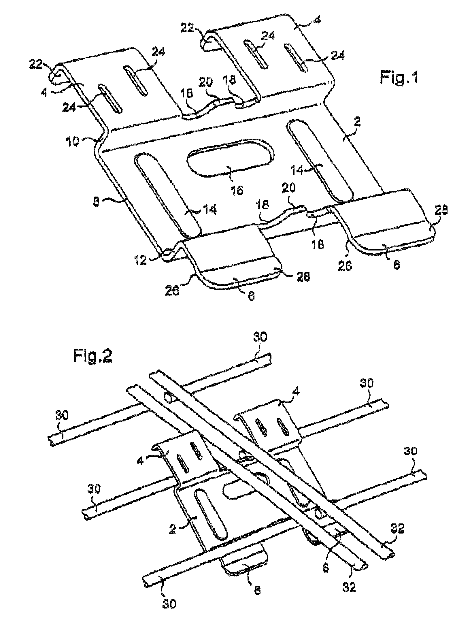
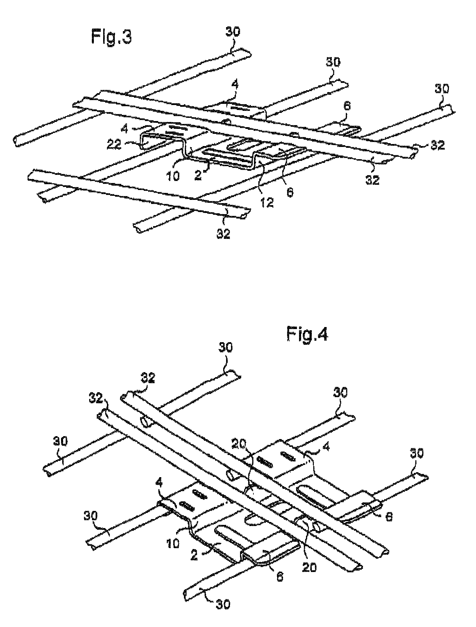
[0027]The drawings represent a preferred embodiment of a connecting splice bar according to the invention. FIG. 1 is a perspective view of this kind of splice bar on its own (the other figures show the same splice bar positioned relative to cable tray sections).

[0028]As can be seen in FIG. 1, the splice bar shown is made from a metal plate (for example a galvanized steel plate) cut and bent to shape. This splice bar has a central part 2 having a profiled shape of U-shaped cross section, from which extend from one side two bearing lugs 4 and from another side two locking lugs 6 referred to hereinafter as clipping lugs.

[0029]As indicated hereinabove, the central part 2 is a profiled portion with a U-shaped cross section. It therefore has a bottom 8, a first lateral branch 10 and a second lateral branch 12.

[0030]Here the bottom 8 has a rectangular shape. That shape appears to be the most suitable here, but other shapes, preferably with two parallel opposite edges, can also be envisaged...


PUM


Abstract

The invention concerns a splice bar for connecting two abutting sections of said cable tray, each cable tray section comprising longitudinal warp yarns and transverse weft yarns connecting the warp yarns. It comprises: an elongated central part (2) having two transverse support zones (18), designed each to receive one weft yarn; two anvil lugs (4) connected to the central part (2) on the same side thereof and arranged on either side of the transverse support zones (18); and two locking lugs (6) connected to the central part (2) on the side opposite to the anvil lugs (4) and arranged on either side of the transverse support zones (18).

Description

FIELD OF THE INVENTION[0001]The present invention concerns a connecting splice bar for cable trays.[0002]The field of the invention is splicing wire cable tray sections. Cable trays are used to support, house and protect elongate members that are generally flexible such as electrical cables but equally tubes, for example pneumatic or hydraulic hoses. In the remainder of the present description, for reasons of simplicity and clarity, only electrical cables are referred to. The invention nevertheless applies to any other type of elongate members such as those referred to above or others such as optical fibers, etc.BACKGROUND OF THE INVENTION[0003]A wire cable tray generally has an elongate shape and a U-shaped section. It includes longitudinal wires, called warp wires, and transverse wires, called weft wires. The warp wires are generally straight and the weft wires U-shaped. All these wires are welded to each other so that they are regularly spaced. This produces a wire cable tray hav...

Claims


Application Information

Patent Timeline
IPC IPC(8): F16B7/04
CPCH02G3/0443H02G3/0608Y10T403/7075Y10T403/7141Y10T403/7001H02G3/04
Inventor QUERTELET, STEPHANEPAREUX, THOMAS
Owner I C M GRP
Features
  • Generate Ideas
  • Intellectual Property
  • Life Sciences
  • Materials
  • Tech Scout
  • Unparalleled Data Quality
  • Higher Quality Content
  • 60% Fewer Hallucinations
Learn More