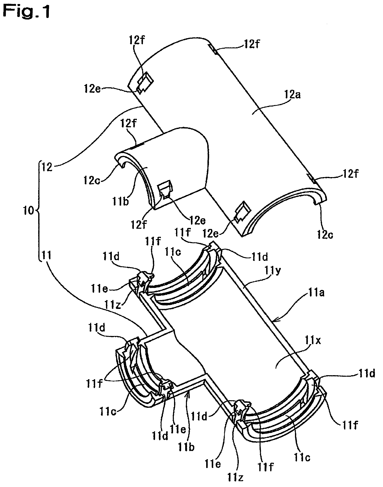
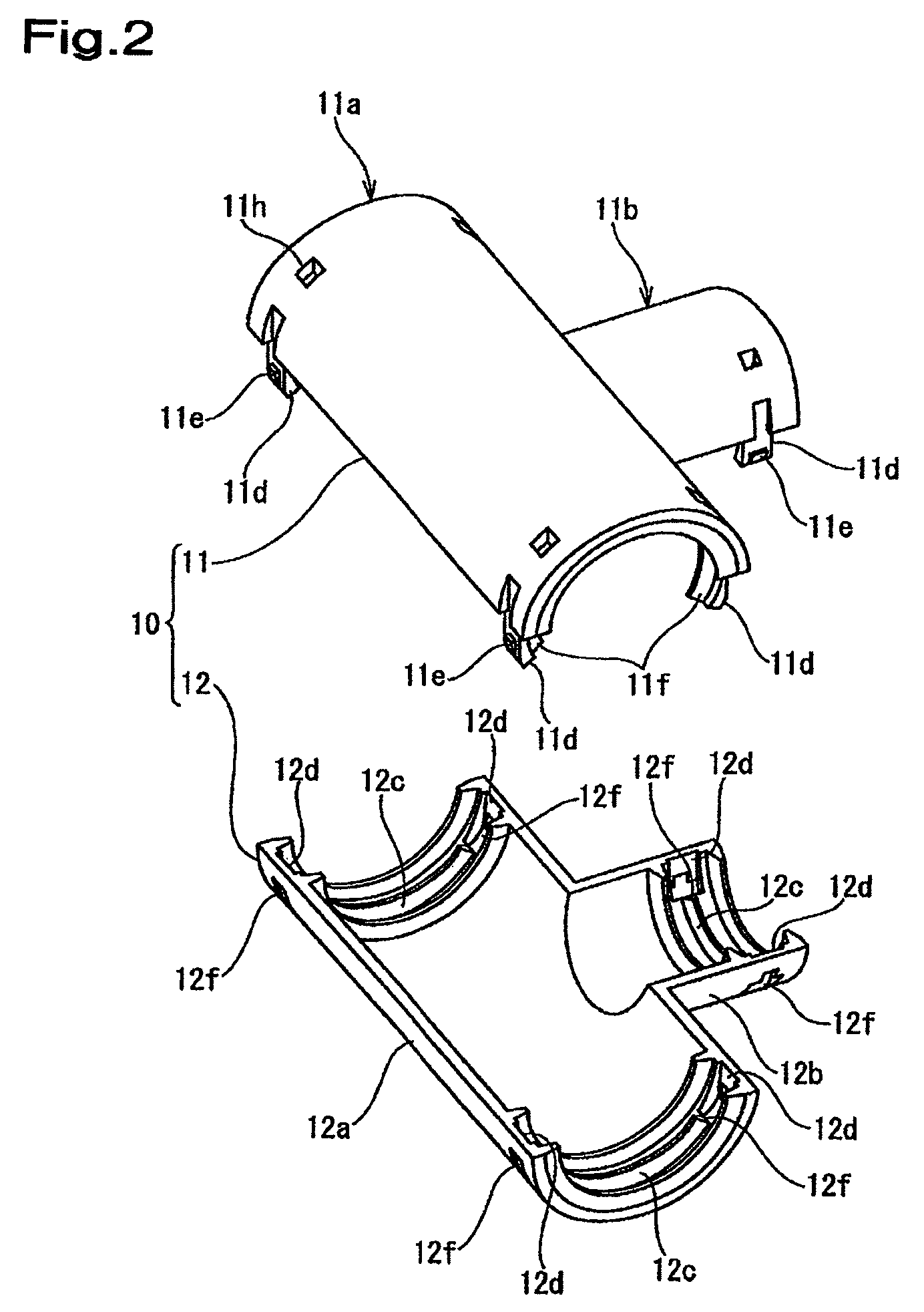
[0011]According to the protector having the previously-described structure, the lock sections project from an inner peripheral surface, not from the outer peripheral surface of the main body. Therefore, the lock sections project to an inner peripheral surface side of the lid body. The lock sections are inserted into the lock holes in the lid body from an inner surface side, causing the lock claws at the lock section tips to engage with the engagement parts of the lock holes. Consequently, the main body and the lid body are joined and locked. At that time, the lock claws do not project from the outer peripheral surface of the lid body while engaging with the engagement parts. Since the lock claws do not interfere with external members, the protector is prevented from being unlocked when the lock claws are pressed by the external members. In addition, the size of the protector can be reduced. The lock sections are disposed along the inner peripheral surface of the lid body to cause the lock claws, which project on the outer surface side of the lock sections, to engage with the engagement parts of the lock holes. When the wire harness that is inserted into the protector presses the protector outwardly from inside, the lock sections are pressed against inner surface of the lid body, causing the lock claws of the lock sections to more firmly engage with the lock holes. Consequently, joining and locking force can be strengthened.
[0012]It is preferred that the above-described lock holes are provided by cutting portions of the inner peripheral part of the peripheral wall of the lid body in parallel to a diametrical direction. It is also preferred that the lock sections project from the inner peripheral part of the peripheral wall of the main body in parallel to the diametrical direction. Having the lock holes and the lock sections both in parallel to the diametrical direction improves matching accuracy of the lock hole direction and the lock section direction, allowing smooth insertion of the lock sections into the lock holes.
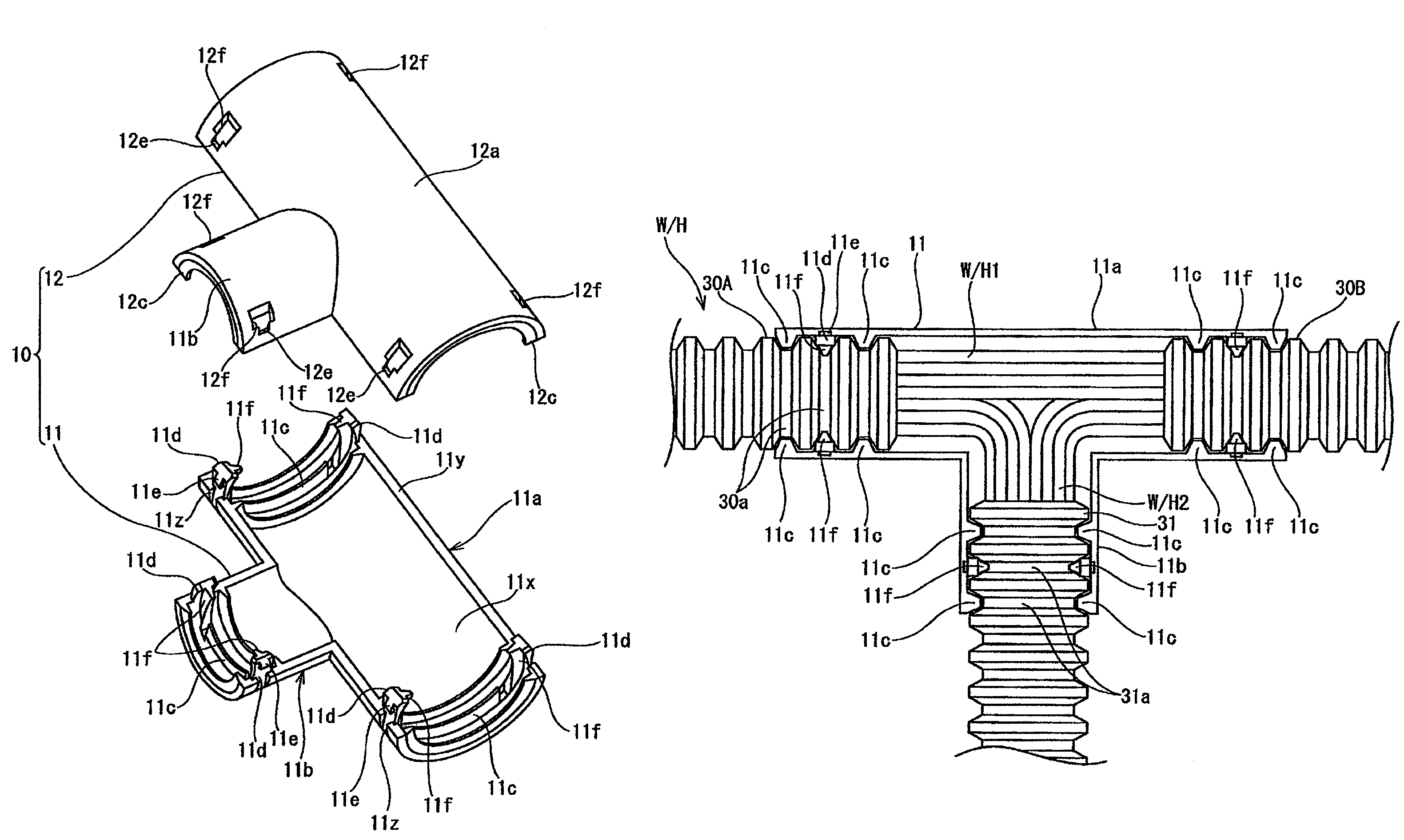
[0013]The wire harness that is inserted into the protector of the present invention is provided with a T-shaped branch part at which branch lines separate from main lines, the main and branch lines being passed through corrugated tubes. The protector is most preferably used to cover the T-shaped branch part of the wire harness. Conventionally, wires of the wire harness are often bound with tape for convergence and protection thereof. The tape binding requires skill and adds to workload. Presently, wires are often passed through corrugated tubes for convergence and protection thereof, the corrugated tubes being provided with crests and recesses alternatively in an axis direction for increased flexibility. However, with the corrugated tubes, the wires that are pulled out of the ends of the corrugated tubes are exposed at a branching point of the wire harness. Therefore, the branch part at which the wires are exposed is covered with the protector.
[0015]Although the structure is complex in which the wire harness separates, the protector is not bulky, since, as described above, the lock parts do not project on an exterior of the protector. The main body and the lid body of the protector that is mounted on the T-shaped branch part are joined and locked multi-directionally. In this type of structure, lock parts tend to interfere with external members. However, the protector is prevented from being unlocked by having the joined and locked parts not projecting outwardly. The protector receives large press force from the wire harness therein when the wire harness is bent at the branch part. However, since the lock sections project to the inner surface side of the lid body, the lock sections do not lose engagement force when being pressed by the inner peripheral surface of the mating body. Therefore, the protector is reliably prevented from being unlocked.
[0018]As described above, the main body is provided with the lock sections that project from edges thereof. In addition, the lock sections are provided with the swelled parts on the inner surface side thereof for fixing the corrugated tubes temporarily. As a wire harness is fitted into the main body while the lid body is still opened, the recesses of the corrugated tubes that cover the wire harness can be pressed and fixed by the swelled parts from an oblique upper direction. Thereby, the corrugated tubes can be prevented from coming out of the inside of the main body. In addition, when the main body and the lid body are joined and locked, operators do not need to hold the corrugated tubes in the main body to position and to fix the corrugated tubes therein. Consequently, the main body and the lid body can be easily joined and locked.
[0019]As described above, according to the protector of the present invention, the lock sections that project from the main body are provided along the inner peripheral side of the lid body. When the main body and the lid body are joined and locked, the lock sections do not project on the outer surface side of the lid body. Therefore, the size of the protector can be reduced. In addition, since the lock sections do not interfere with external members, the protector is prevented from being unlocked. Moreover, when the wire harness that is inserted into the protector presses the protector outwardly from inside, the lock sections are pressed against the inner surface of the lid body, causing the lock claws of the lock sections to more firmly engage with the lock holes. Consequently, joining and locking force can be strengthened.

