Door lock release mechanism for automobile door

a technology for automobile doors and release levers, which is applied in the direction of doors, locks, wing knobs, etc., can solve the problems of door opening and durability of release levers

Inactive Publication Date: 2012-05-17
TOYOTA SHATAI KK
View PDF13 Cites 12 Cited by
  • Summary
  • Abstract
  • Description
  • Claims
  • Application Information

AI Technical Summary

Benefits of technology

[0018]In this configuration, deformation of the vehicle door caused by a side collision moves the lock release prevention member to a position on the path of the opening operation of the opening rod of the latch open lever. This allows the unlocking prevention member to directly restrict the opening operation of the latch open lever.

Problems solved by technology

As a result, through the side collision, the associated latch open lever may operate to release the door lock, thus causing the door to open.
This causes a problem in durability of the release lever, which includes the fragile portion.

Method used


Image

  • Door lock release mechanism for automobile door
  • Door lock release mechanism for automobile door
  • Door lock release mechanism for automobile door

Examples


first embodiment

[0045]In the first embodiment, the spacer 40 is formed by a block, which is a solid body. However, the spacer 40 is not restricted to being formed by a block but may be formed by a frame body in a three-dimensional manner.

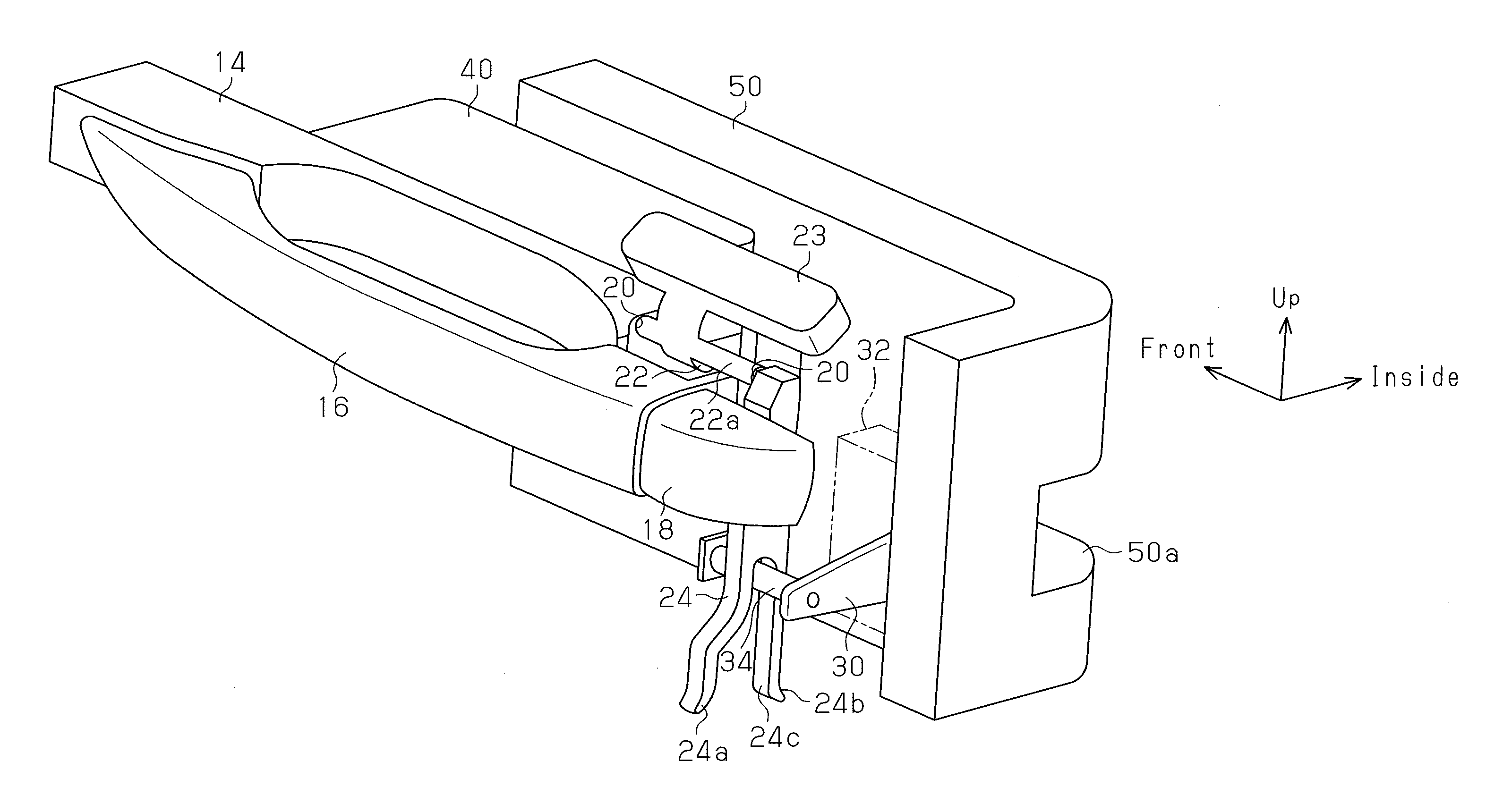
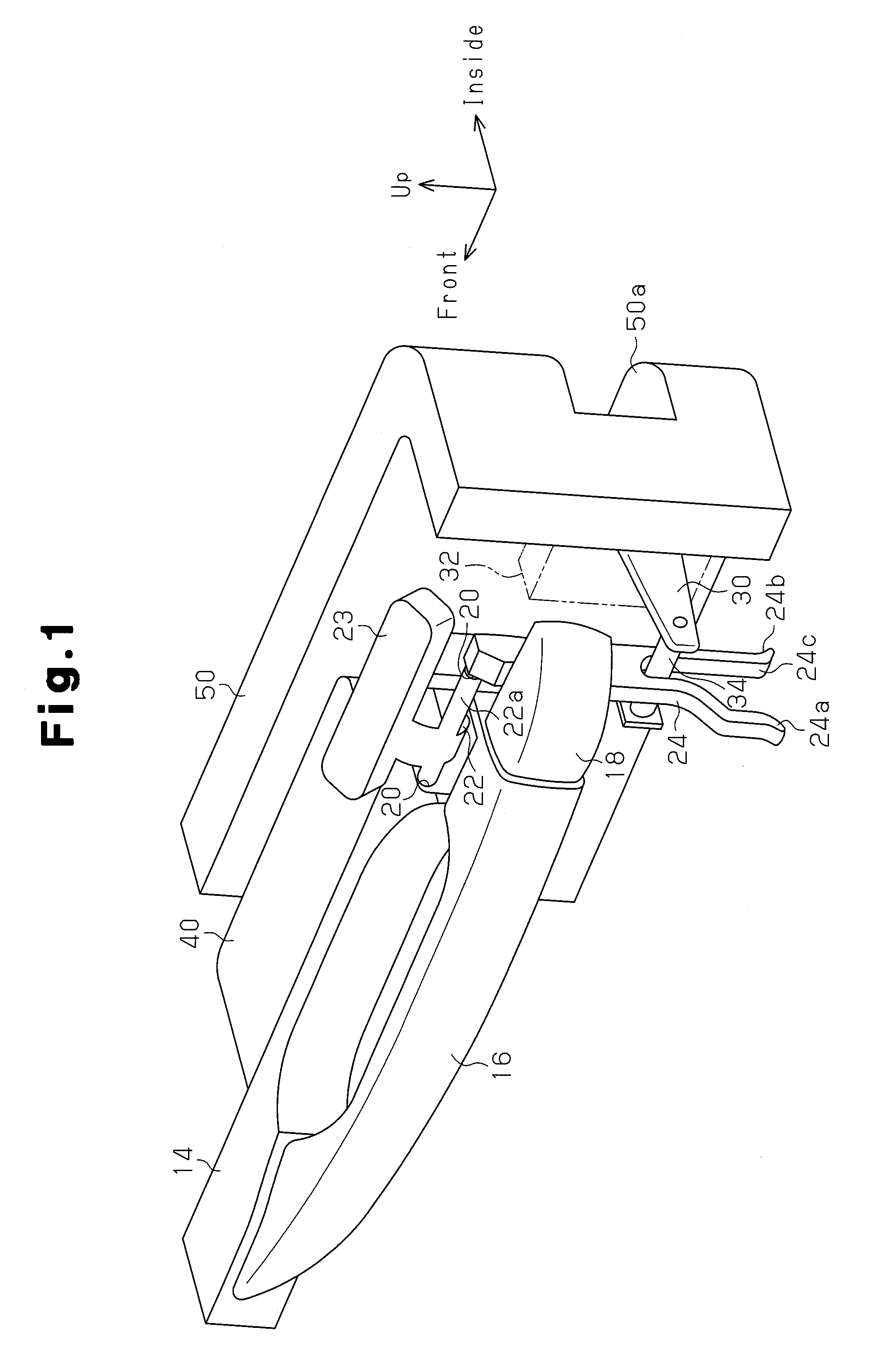
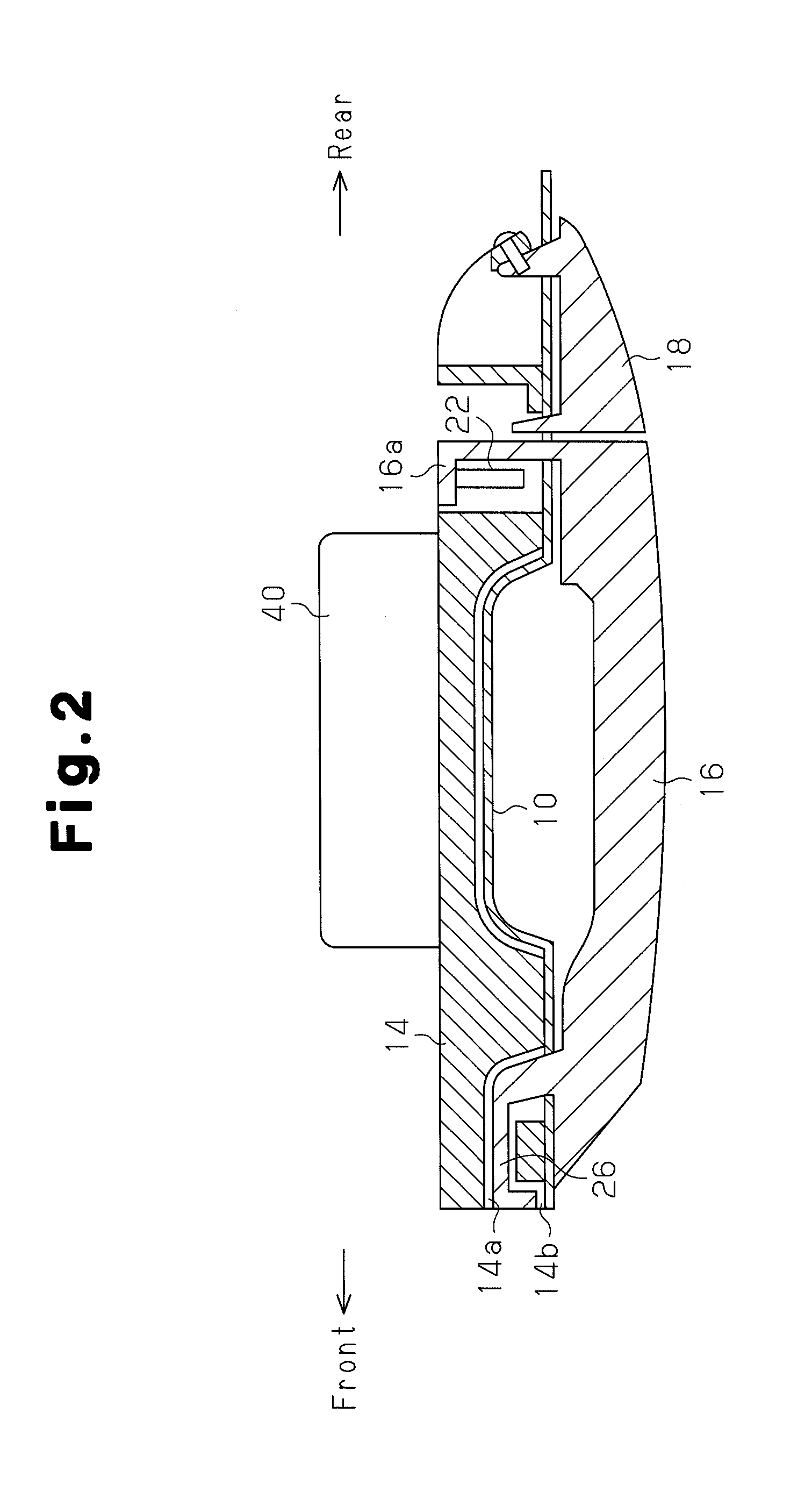
[0046]The outside handle 16, the handle base 14, the spacer 40, the bell crank 22, and the counterweight 23 configure a handle unit.

[0047]As illustrated in FIG. 3, an engagement portion 40a serving as a lock release prevention member is projected from the side surface of the spacer 40 facing the release lever 24 in the extending direction of the shaft 22a. During a normal time, which is when the outside handle 16 is not manipulated and a side collision does not happen, the engagement portion 40a is arranged at a position spaced from a claw portion 24d of the release lever 24, as shown in FIG. 3. Also when the outside handle 16 is manipulated to open the door, as illustrated in FIG. 4, the engagement portion 40a is arranged at a position spaced from the claw portion...

second embodiment

[0062]Both at a normal time when there is no side collision, that is, when the outside handle 16 is not operated, and at the time when the outside handle 16 is operated, the preventing portion 60a is spaced from the opening rod 34, with reference to FIG. 10. The preventing portion 60a is thus arranged at such a position that the preventing portion 60a is maintained outside the operating path of the opening rod 34 at the time of a downward opening operation of the latch open lever 30 and the opening rod 34. Specifically, in the second embodiment, the path of the opening operation of the latch open lever 30 includes the operating path of the opening rod 34.

[0063]When the vehicle is involved in a side collision, as illustrated in FIG. 11, the handle unit as a whole, including the outside handle 16, the handle base 14, the spacer body 40, the bell crank 22, and the counterweight 23, is displaced in the outward direction of the vehicle due to inertial force acting in the direction repres...

third embodiment

[0075]The third embodiment has the characteristics described below.

[0076](7) In the door lock release mechanism of the third embodiment, the extended portion 60 is formed integrally with the handle base 14 (the fixed component) as the spacer. The extended portion 60 is arranged outward in the vehicle body compared to the latch open lever 30. Also, the preventing portion 60a (the lock release prevention member) is formed in the extended portion 60 and arranged outside the path of the opening operation of the latch open lever 30 in a normal time. The preventing portion 60a is moved to a position on the path of the opening operation of the latch open lever 30 when the vehicle door deforms in a side collision. The preventing portion 60a thus restricts the opening operation of the latch open lever 30.

[0077]That is, deformation of the vehicle door caused by the side collision sends the preventing portion 60a to a position on the path of the opening operation of the latch open lever 30. Th...


PUM


Abstract

A door lock release mechanism includes a spacer 40, which is fixed to a handle base 14 and restricts depression of an outside handle in an inward direction of a vehicle when a door of the vehicle is deformed, and an engagement portion 40a, which is formed in the spacer 40 and arranged at a position outside the normal path of an opening operation of the door lock release mechanism. The engagement portion 40a is moved to a position in the path of the opening operation of the door lock release mechanism to restrict the opening operation of a latch open lever 30 through deformation of the door of the vehicle when a side collision occurs. As a result, simply through the engagement portion 40a formed in the spacer 40, which restricts displacement of the outside handle 16 in the inward direction of the vehicle, the unlocking operation of the latch open lever 30 is prevented to avoid unlocking of the door when the door is deformed through the side collision.

Description

TECHNICAL FIELD[0001]The present invention relates to a door lock release mechanism for a vehicle door.BACKGROUND ART[0002]Outside door handles for vehicle doors include pull-up type handles and grip-type handles. The pull-up types are pivotally supported in such a manner as to allow manipulation in a vertical direction. The grip-types are pivotally supported in such a manner as to allow manipulation in a horizontal direction.[0003]A grip type outside handle includes a link lever, which is linked to the outside handle, and a release lever connected to the link lever. A latch open lever is linked to the release lever. When the outside handle is manipulated in an opening direction, which is a direction separating from a door outer panel (hereinafter, referred to as an “outer panel”), the latch open lever is operated through the link lever and the release lever to release the door lock.[0004]In a vehicle involved in a side collision, an outside handle may displace in the opening direct...

Claims


Application Information

Patent Timeline
Patent Type & Authority Applications(United States)
IPC IPC(8): E05B65/20B60J5/04E05B83/36B60J5/00E05B1/00E05B77/04
CPCE05B77/04E05B77/06Y10S292/65Y10S292/22E05B85/16Y10T292/0908Y10T292/57
Inventor SAKAI, YASUNARIYAMAMOTO, TAKAOMIZUTA, TOMOCHIKA
Owner TOYOTA SHATAI KK
Why Eureka
Try Eureka