
Tone hopping methods and apparatus

a technology of tones and apparatus, applied in the field of communication systems, to achieve the effect of limiting the number of collisions

Active Publication Date: 2010-05-11
QUALCOMM INC
View PDF61 Cites 13 Cited by
  • Summary
  • Abstract
  • Description
  • Claims
  • Application Information

AI Technical Summary

Benefits of technology

[0025]The functions used to allocate tones to uplink tone hopping functions in accordance with the present invention are selected to minimize repeated collisions between uplink tone hopping sequences in a predictable manner even when the tones, e.g., frequencies, used for transmission in neighboring base stations are misaligned. Such frequency misalignment may be due to base station clock errors or other frequency discrepancies between base stations.
[0029]The difference between the first and second functions may be as simple as the use of a different constant value by the first base station to distinguish between the first and second sectors when implementing the function used to allocate tones to tone hopping sequences. The constant value used to implement a base station's tone allocation function may be stored in the base station's memory as well as the memory of wireless terminals within the cell which includes the base station.
[0030]The difference between the first and third functions or second and third functions may be as simple as the use of a different constant value by each of the first and second base stations when implementing the function used to allocate tones to tone hopping sequences. The constant value used to implement a base station's tone allocation function may be stored in the base station's memory as well as the memory of wireless terminals within the cell which includes the base station.
[0037]Using the above function with different constant values T in adjacent sectors of a base station, it is possible to limit the number of collisions between hopping sequences of adjacent sectors in a manner that allows the tones of any one hopping sequence in the first set of P hopping sequences used by a first base station in the first sector to collide with any one hopping sequence in a second set of P hopping sequences used by a base station in a second, adjacent, sector at most once during any P sequential tone allocation periods, where P is a constant value indicating the number of tones allocated within a cell using the above function during a single tone allocation period.
[0038]Using the above function with different constant values s in neighboring base stations, it is possible to limit the number of collisions between hopping sequences of neighboring base stations in a manner that allows the tones of any one hopping sequence in the first set of P hopping sequences used by a first base station to collide with any one hopping sequence in a third set of P hopping sequences used by a neighboring base station at most twice during any P sequential tone allocation periods, where P is a constant value indicating the number of tones allocated within a cell using the above function during a single tone allocation period.
[0043]In some embodiments of the invention, the uplink tone hopping sequence is truncated before full completion, i.e., allocation of tones according to the first, second or third function repeats over a time interval shorter than P allocation periods, and restarted, thus enabling faster synchronization to wireless terminal which may become active at any random time.

Problems solved by technology

Such frequency misalignment may be due to base station clock errors or other frequency discrepancies between base stations.

Method used


Image

  • Tone hopping methods and apparatus
  • Tone hopping methods and apparatus
  • Tone hopping methods and apparatus

Examples


Embodiment Construction

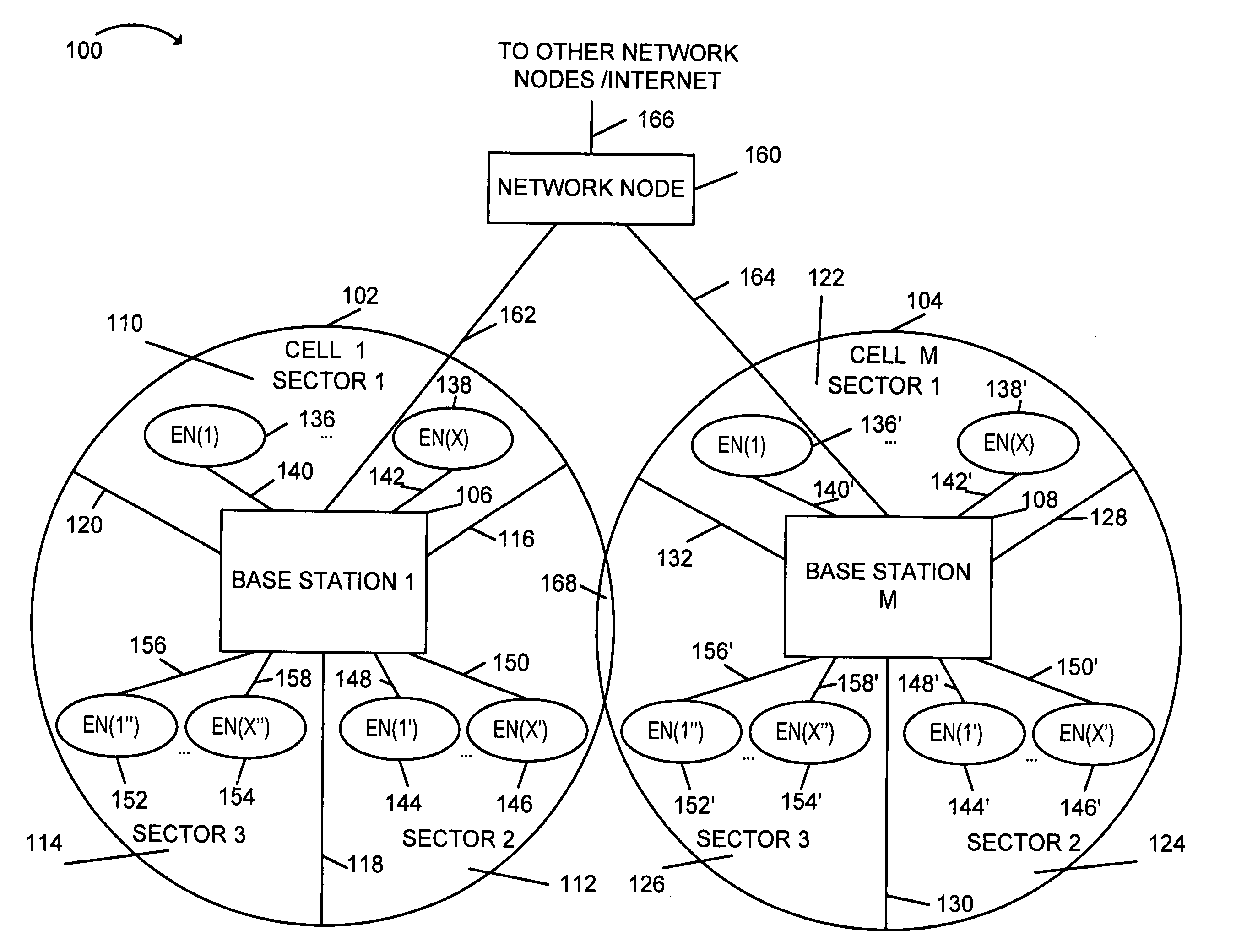
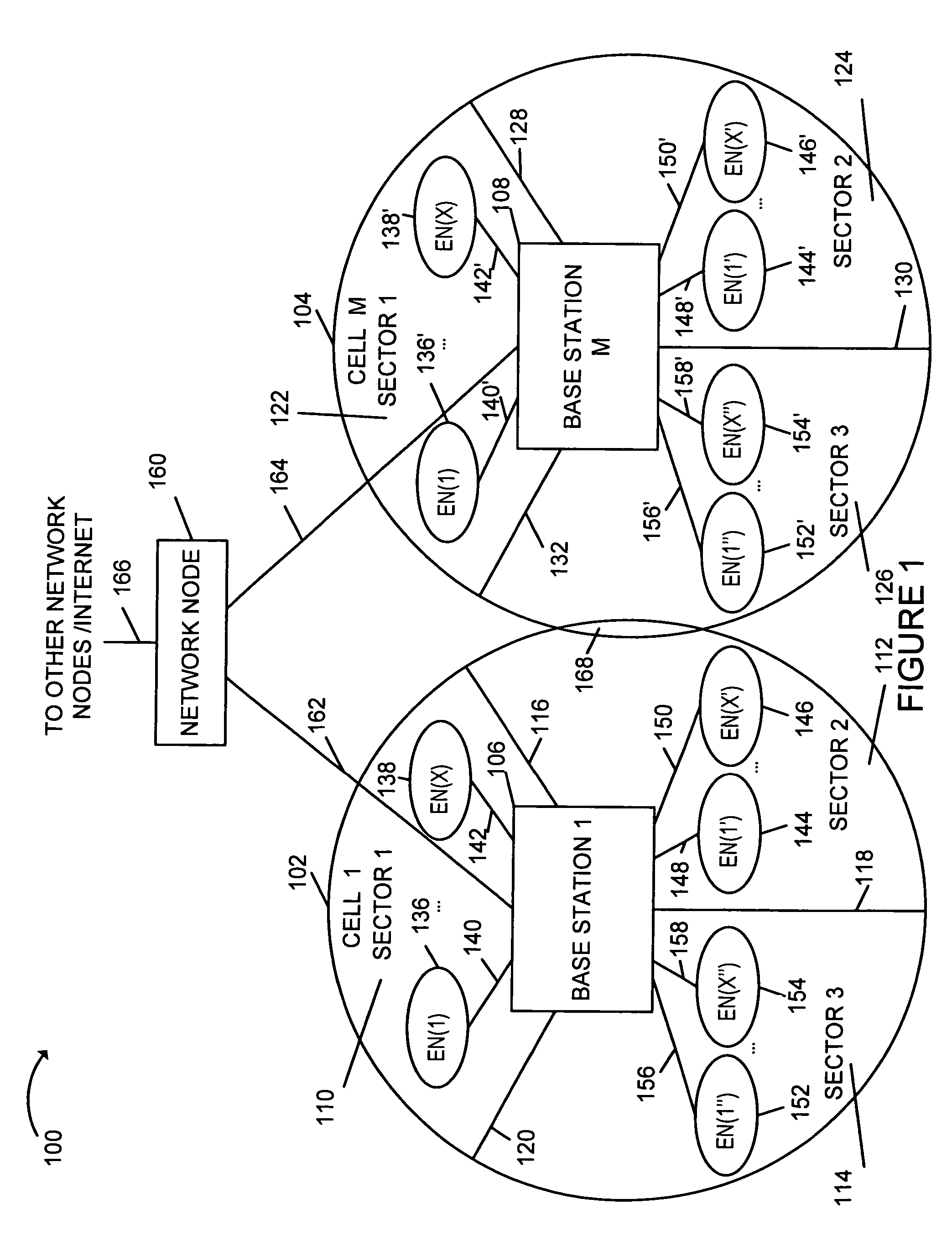
[0048]FIG. 1 shows an exemplary communication system 100 implemented in accordance with the present invention including multiple cells: cell 1102, cell M 104. Note that neighboring cells 102, 104 overlap slightly, as indicated by cell boundary region 168, thereby providing the potential for signal collisions between signals being transmitted by wireless devices in neighboring cells. Each cell 102, 104 of exemplary system 100 includes three sectors. Cells which have not be subdivided into multiple sectors (N=1), cells with two sectors (N=2) and cells with more than 3 sectors (N>3) are also possible in accordance with the invention. Cell 102 includes a first sector, sector 1110, a second sector, sector 2112, and a third sector, sector 3114. Each sector 110, 112, 114 has two sector boundary regions; each boundary region is shared between two adjacent sectors. Sector boundary regions provide the potential for signal collisions between signals being transmitted by wireless devices in nei...


PUM


Abstract

Methods and apparatus for allocating and hopping tones for uplink communications purposes in adjacent sectors and neighboring cells of an OFDM system are described. Physical tones used in each sector and cell are allocated to tone hopping sequences according to a tone to tone hopping sequence allocation function which uses both a cell identifier and sector identifier. Different sectors and cells use different tone to tone hopping sequence allocation functions through the use of different cell and / or sector identifiers to minimize the number of collisions between hopping sequences of adjacent sectors and neighboring cells. Uplink tone hopping sequences, corresponding to logical tones are allocated to uplink communications channels. Uplink communications channels are used by wireless terminals, e.g., mobile nodes, to transmit data to base stations. Over time, a wireless terminal uses the tones included in the uplink tone hopping sequences corresponding to uplink communications channels it is authorized to use.

Description

RELATED APPLICATIONS[0001]The present application is a continuation-in-part of U.S. patent application Ser. No. 10 / 965,011 filed Oct. 14, 2004 which issued as U.S. Pat. No. 7,379,446 and claims the benefit of U.S. Provisional Patent Application Ser. No. 60 / 717,701, filed on Sep. 16, 2005, titled “TONE HOPPING METHODS AND APPARATUS”, which is hereby expressly incorporated by reference.FIELD OF THE INVENTION[0002]The present invention relates to communications systems and, more particularly, to methods and apparatus for allocating tones, e.g., in a cellular communications network.BACKGROUND[0003]In a cellular wireless system, a service area is divided into a number of coverage zones generally referred to as cells. Each cell may be further subdivided into a number of sectors. Wireless terminals in a cell communicate with the base station that serves the cell. Wireless terminals may include a wide range of mobile devices including, e.g., cell phones and other mobile transmitters such as...

Claims


Application Information

Patent Timeline
Patent Type & Authority Patents(United States)
IPC IPC(8): G06F15/00H04B1/713
CPCH04B1/713H04L27/2601H04W16/12H04W16/02H04W16/24H04J11/00
Inventor JIN, HUILI, JUNYI
Owner QUALCOMM INC
Learn More