Dual printhead assembly and 3D printing apparatus using same

a printing apparatus and printhead technology, applied in the field of printhead assembly, can solve the problems of difficult installation or adjustment of the installation or adjustment of the conventional dual printhead assembly of the fdm apparatus, the limitation of the shape variation of the fdm technique, and the difficulty of fdm apparatus to produce unsupported stalactites, etc., to achieve the effect of simple structure, easy assembly and simplified assembling process

Active Publication Date: 2019-11-05
TECO IMAGE SYST
View PDF5 Cites 0 Cited by
  • Summary
  • Abstract
  • Description
  • Claims
  • Application Information

AI Technical Summary

Benefits of technology

[0007]An object of the present invention is to provide a dual printhead assembly and a 3D printing apparatus using the same. The dual printhead assembly has the advantages of simple structure and being assembled easily. The dual printhead assembly can be installed and replaced by controlling a single bolt easily, and a mutual height difference of the dual printhead assembly can be adjusted by controlling the rotating cams to drive a positioning swing arm of the dual printhead assembly. Thereby, the assembling process is simplified effectively, the cost is saved and the operational efficiency is improved.
[0008]Another object of the present invention is to provide a dual printhead assembly and a 3D printing apparatus using the same. While the dual printhead assembly is driven to move by the driving unit of the 3D printing apparatus automatically, the status of the rotating cams can be controlled to drive the positioning swing arm. Consequently, the positioning swing arm can be swung to adjust the mutual height difference of the dual printhead assembly There is no need to add an extra independent driving source for driving the rotating cams or a height sensing unit for detecting the height difference. Consequently, the operation of the dual printhead assembly for switching the mutual height difference is simplified effectively and the operational efficiency is improved.
[0009]A further object of the present invention is to provide a dual printhead assembly and a 3D printing apparatus using the same. While the rotating cams are controlled to drive the positioning swing arm of the dual printhead assembly for adjusting the mutual height difference thereof, the non-use nozzle of the dual printhead assembly can be switched to press against an elastic arm for preventing the cooling materials from overflowing. Consequently, the raw materials waste and the defects on the working piece are avoided. In addition, the nozzle in use can be performed to print continuously, instead of stopping and waiting for completely cooling the materials in the non-use nozzle. The waste of operating time can be reduced effectively, and the operational efficiency of the dual printhead assembly is improved.
[0010]An additional object of the present invention is to provide a dual printhead assembly and a 3D printing apparatus using the same. The dual nozzle assembly is driven to move relative to a switch pin set by the driving unit of the 3D printing apparatus so that the dual printhead assembly can accomplish the nozzle switching operation of the dual printhead assembly without using additional driving sources. Not only the cost is saved, but also the operational efficiency of the dual printhead assembly and the 3D printing apparatus is improved.

Problems solved by technology

Although FDM technique is very flexible for producing 3D model or parts, FDM technique still has some restrictions in the variation of shapes that may be fabricated.
For example, it is difficult to produce unsupported stalactites, because the extruding material can't be supported by the printed and hardened parts during the printing process.
Hence, it is difficult to execute the installation or adjustment for the conventional dual printhead assembly of the FDM apparatus.
Further, the mutual heights of the two single printhead sets are unchangeable and always kept in the same plane during the FDM printing.
When the printing program is executed, if the nozzle of another non-use single printhead set scratches the working piece, it will lead to print operations failed.
Since the hot material easy to overflow from the nozzle of the single printhead set during cooling, it is necessary to move the dual printhead assembly to a waste box for waiting the temperature to cool down and it must take a lot of time.

Method used


Image

  • Dual printhead assembly and 3D printing apparatus using same
  • Dual printhead assembly and 3D printing apparatus using same
  • Dual printhead assembly and 3D printing apparatus using same

Examples


Embodiment Construction

[0031]The present invention will now be described more specifically with reference to the following embodiments. It is to be noted that the following descriptions of preferred embodiments of this invention are presented herein for purpose of illustration and description only. It is not intended to be exhaustive or to be limited to the precise form disclosed.

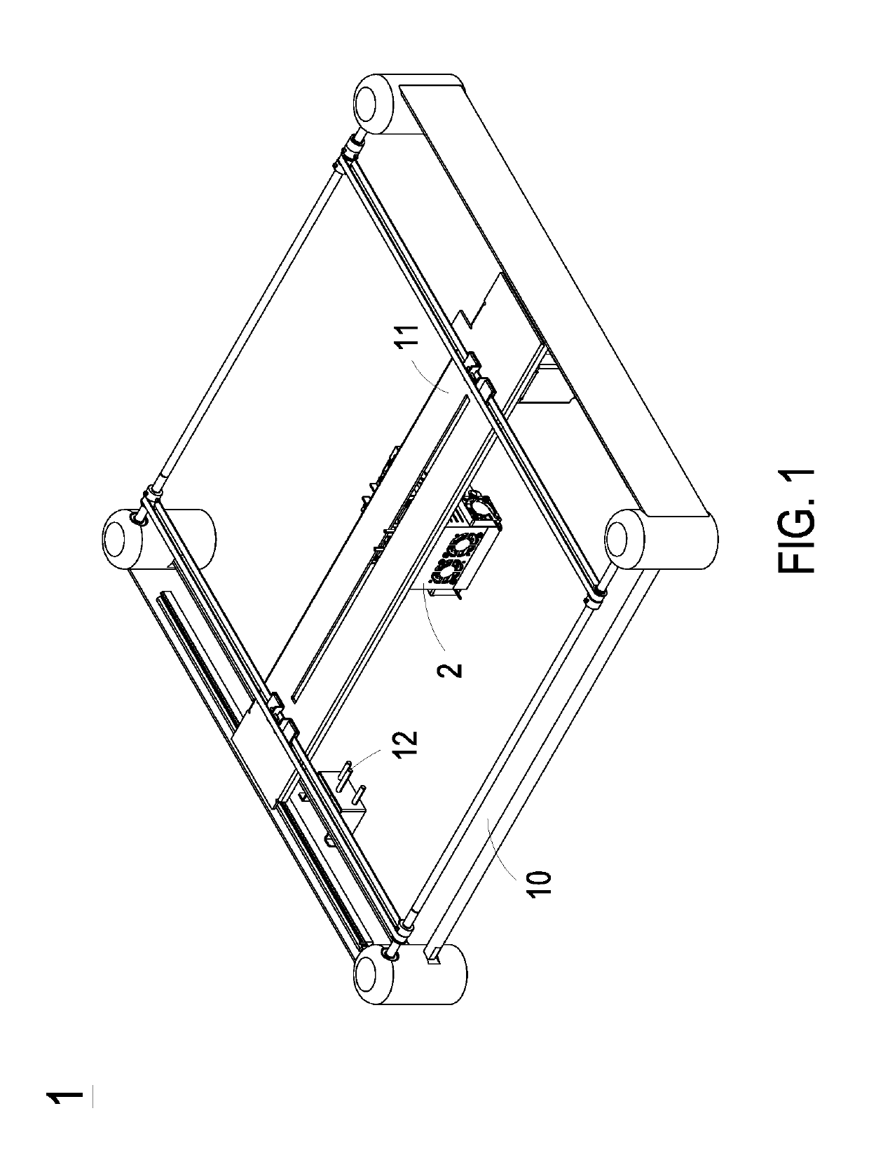
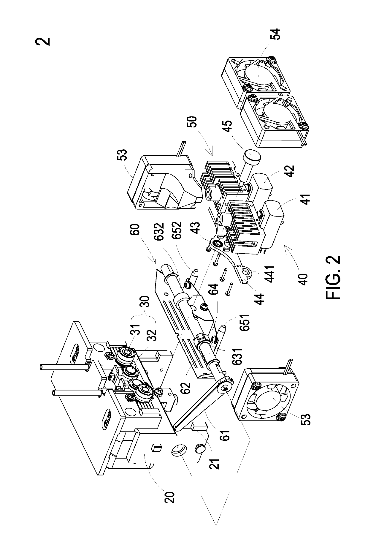
[0032]FIG. 1 is a perspective view illustrating a 3D printing apparatus according to a preferred embodiment of the present invention. The 3D printing apparatus 1 includes a frame 10, a driving unit 11, a switching pin set 12 and a dual printhead assembly 2. The switching pin set 12 is disposed on an edge of the frame 10. The driving unit 11 is constructed on the frame 10. The dual printhead assembly 2 is constructed on the driving unit 11 and driven by the driving unit 11 to move to a specific working position in the frame 10 for executing a 3D printing process or an adjustment process. FIG. 2 is an exploded view illustrating a d...


PUM

PropertyMeasurementUnit
heightaaaaaaaaaa
lengthaaaaaaaaaa
Fused deposition modelingaaaaaaaaaa

Abstract

The disclosure relates to a dual printhead assembly and a 3D printing apparatus. The dual printhead assembly includes a base, a printhead module and a switching module. The printhead module includes a positioning swing arm with a bearing disposed at the middle portion thereof, a first printhead unit and a second printhead unit fixed nearby two opposite edges of the bearing, respectively, and a fixing piece passing through the bearing to assemble the printhead module on the base. While a rotation shaft of the switching module is rotated to drive a first cam or a second cam to press an end or another end of an elastic sheet, a third or fourth connecting element disposed on the elastic sheet is driven to press an end or another end of the positioning swing arm, so as to adjust the height difference between the first printhead unit and the second printhead unit.

Description

FIELD OF THE INVENTION[0001]The present invention relates to a printhead assembly, and more particularly to a dual printhead assembly and a 3D printing apparatus using the same.BACKGROUND OF THE INVENTION[0002]3D printing, also known as additive manufacturing (AM), refers to processes used to create a three-dimensional object. A large number of additive processes are available in the current market. The main differences between processes are in the way of depositing layers to create parts and in the used materials. Fused deposition modeling (FDM) is an additive manufacturing technology commonly used for modeling, prototyping, and production applications. In Fused deposition modeling (FDM), the model or part is produced by extruding streams of thermoplastic materials, which harden immediately to form layers. A plastic filament or metal wire is unwound from a coil and supplies material to an extrusion nozzle head (3D printer extruder), which heats the material and turns the flow on an...

Claims


Application Information

Patent Timeline
Patent Type & Authority Patents(United States)
IPC IPC(8): B29C64/236B29C64/295B29C64/209B33Y30/00B29C64/118
CPCB29C64/236B29C64/209B33Y30/00B29C64/118B29C64/295
Inventor CHEN, TING-CHUN
Owner TECO IMAGE SYST
Why Eureka
Try Eureka