
Airbag arrangement

a technology for airbags and seats, applied in the direction of pedestrian/occupant safety arrangements, vehicle safety belts, vehicle components, etc., can solve the problems of substantial restraint and very sudden acceleration of vehicles

Active Publication Date: 2010-05-18
AUTOLIV DEV AB
View PDF16 Cites 112 Cited by
  • Summary
  • Abstract
  • Description
  • Claims
  • Application Information

AI Technical Summary

Benefits of technology

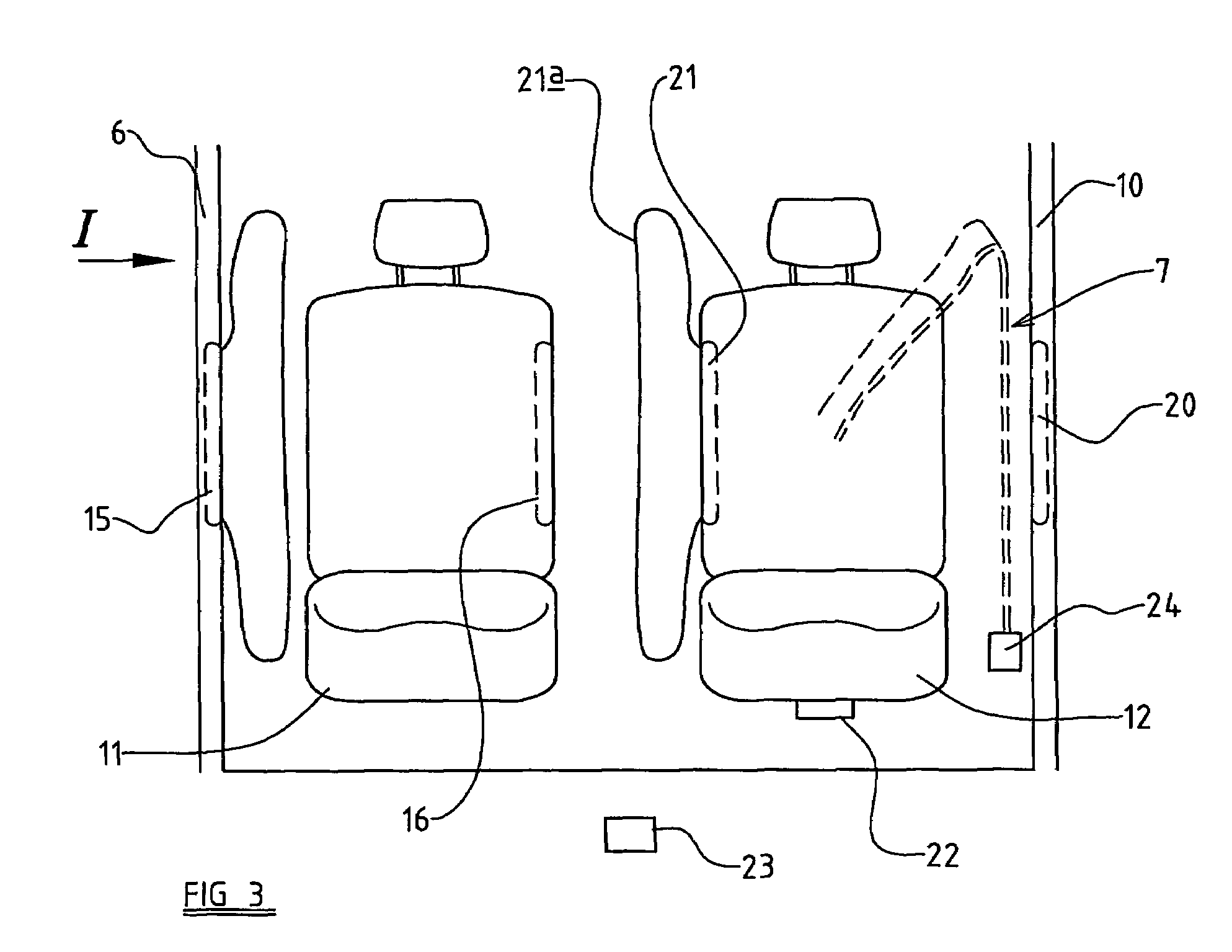
[0007]According to the present invention, there is provided an air-bag arrangement in a motor vehicle to provide protection for the occupant of at least one seat, the seat being associated with two side impact air-bag units, one air-bag unit containing an air-bag to be deployed to occupy a space on the inboard side of the seat (closest to the center of the vehicle) and the other air-bag unit containing an air-bag to be deployed to occupy a space on the outboard side of the seat (nearest the vehicle door), there being a sensor and control arrangement to sense a side impact and to determine which side of the vehicle has been impacted, and to generate actuation signals capable of actuating only the air-bag unit closest to the point of impact.
[0008]Preferably, the side impact air-bag arrangement is configured to provide protection for the occupants of two seats arranged adjacent one another, wherein the sensor and control arrangement is configured to generate actuation signals capable of actuating only the side impact air-bag unit associated with the first seat closest to the point of impact, and only the air-bag unit of the second seat closest to the point of impact.

Problems solved by technology

When a side impact occurs, from one side of the vehicle, the vehicle is given a very sudden acceleration.
However, for a seat occupant sitting on the side of the vehicle furthest from the side impact, the torso of the occupant will tend to move away from the adjacent “B”-Post, and will not be restrained to a substantial extent by the shoulder belt strap.

Method used


Image

  • Airbag arrangement
  • Airbag arrangement
  • Airbag arrangement

Examples


Embodiment Construction

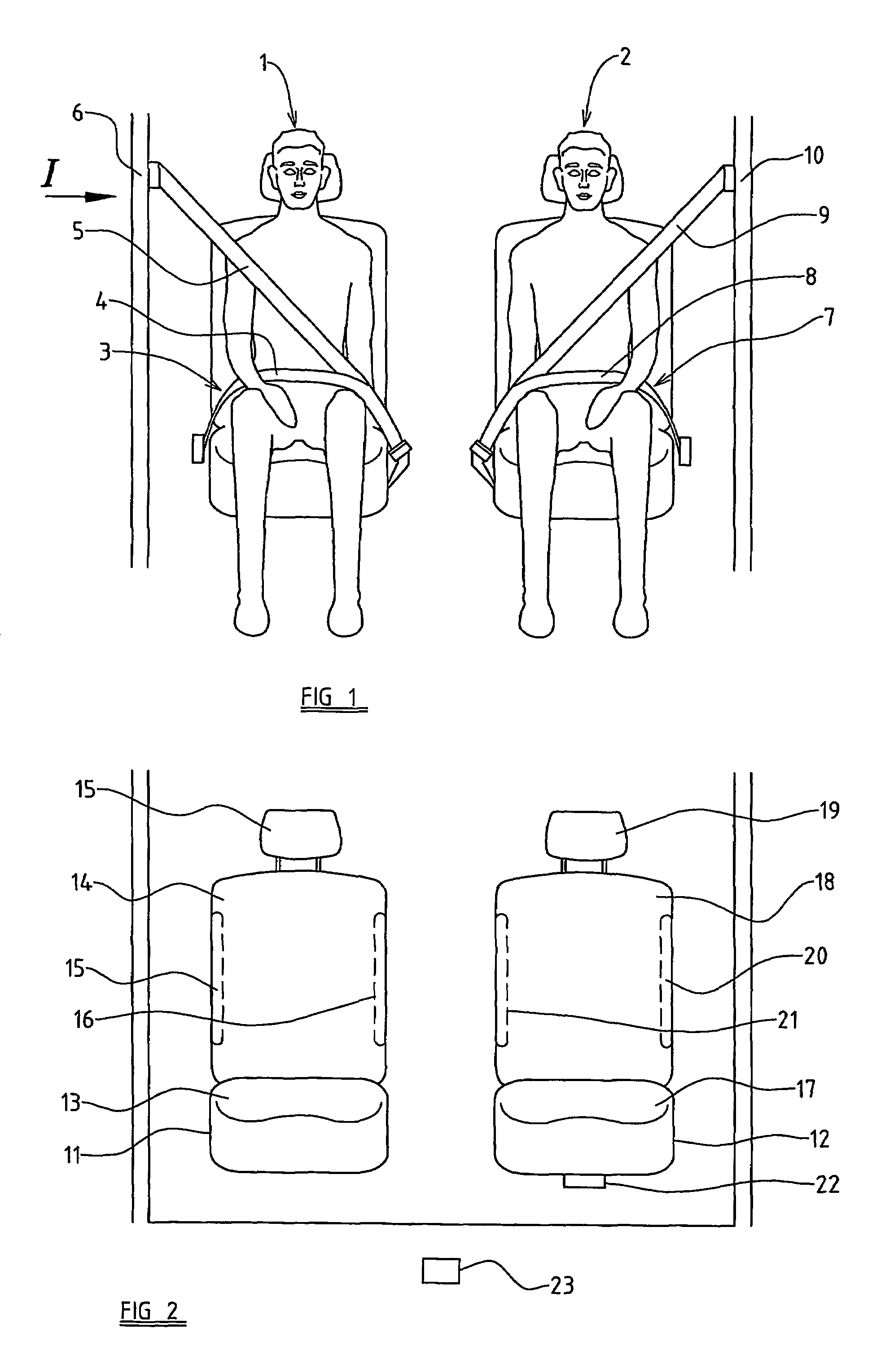
[0026]Referring initially to FIG. 1 of the accompanying drawings, two occupants 1, 2 are illustrated seated in the front seats of a motor vehicle. The first occupant 1 is restrained by a three-point seat-belt 3 which includes a lap strap 4 and a diagonal chest or torso strap 5 (shoulder belt) which extends to an anchoring point, typically in the form of a pillar-loop adjuster, mounted on the adjacent B-Post 6 of the vehicle. Similarly the second occupant, 2 is restrained by a seat-belt 7 which includes a lap strap 8, and a diagonal chest strap 9 (or shoulder belt) which extends across the chest or torso of the occupant to an anchoring point, again typically in the form of a pillar-loop adjuster, provided on opposite the “B”-Post 10 of the vehicle.

[0027]It is to be appreciated that if the vehicle is involved in a side impact, as indicated by the arrow 1, which might be caused by another vehicle hitting the side of the vehicle in question adjacent the first occupant 1, the vehicle wil...


PUM


Abstract

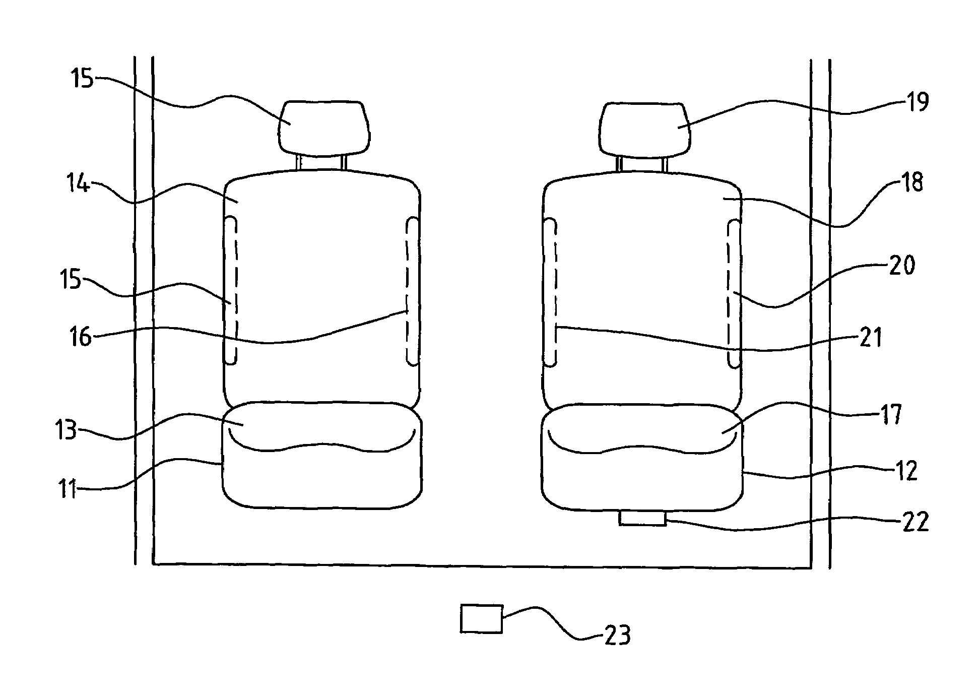
An air-bag arrangement for a motor vehicle is disclosed to provide protection for the occupants (1, 2) of two adjacent seats (11, 12). Each seat is associated with two air-bag units (15, 16, 20, 21), one of which contains an air-bag to be deployed so as to occupy a space on the inboard side of the seat, and the other of which contains an air-bag to be deployed so as to occupy a space on the outboard side of the seat. There is a sensor and control arrangement (23) to sense impact and to determine which side of the vehicle has been impacted. The sensor and control arrangement (23) generates actuation signals capable of actuating the air-bag unit (15) associated with the first seat (11) closest to the point of impact I, and the air-bag unit (21) of the second seat (12) closest to the point of impact I.

Description

CROSS REFERENCE TO RELATED APPLICATIONS[0001]This application claims priority to European patent application 03252579.2, filed Apr. 24, 2003 and PCT / GB2004 / 001641, filed Apr. 15, 2004.FIELD OF THE INVENTION[0002]The present invention relates to an air-bag arrangement, and more particularly relates to an air-bag arrangement intended to provide protection for the occupants of a motor vehicle in the event that a side impact should occur.BACKGROUND OF THE INVENTION[0003]When a side impact occurs, from one side of the vehicle, the vehicle is given a very sudden acceleration. The effect is that, due to inertia, occupants of the vehicle tend to move towards the side of the vehicle where the impact occurs.[0004]Typically a vehicle occupant is restrained by a three-point seat-belt. Typically a three-point seat-belt has a lap belt portion and a diagonal shoulder belt strap, the shoulder belt portion typically extending from a point adjacent the centre of the vehicle upwardly across the chest ...

Claims


Application Information

Patent Timeline
Patent Type & Authority Patents(United States)
IPC IPC(8): B60R21/16B60R21/01B60R21/013B60R21/231
CPCB60R21/23138B60R21/013B60R2021/23146B60R2021/23107B60R21/207B60R22/023
Inventor BOSTROM, OLAHALAND, YNGVE
Owner AUTOLIV DEV AB
Learn More