3-D image display unit, 3-D image recording device and 3-D image recording method

a display unit and image technology, applied in the field of 3d image display units, can solve the problems of unsatisfactory user's intention to turn off the power, the unit cannot cope with carefully thought-out adjustment, and the conventional technique has not permitted the broadcasting station to set a limit time for continuously displaying 3-d images, etc., to reduce the parallax, reduce the burden on the user's eyes, and reduce the effect of large parallax

Inactive Publication Date: 2010-05-18
SHARP KK
View PDF26 Cites 22 Cited by
  • Summary
  • Abstract
  • Description
  • Claims
  • Application Information

AI Technical Summary

Benefits of technology

[0008]Under such circumstances, it is an object of the present invention to provide a 3-D image display unit that can control 3-D images easily and flexibly to protect the user from eyestrain.
[0042]Furthermore, according to the 3-D image format data, the information for denoting an user's 3-D image appreciation allowable time and a continuous 3-D image appreciation allowable time without changing the parallax can be included in the 3-D image control information of the 3d image format data, thereby the information can be transmitted together with image data. The 3-D image display unit is thus very easy to operate.

Problems solved by technology

In other words, the unit cannot cope with carefully thought-out adjustment, for example, adjustment for easing the user's eye burden by reducing the parallax step by step in such a case.
For example, in case of a display unit that can display images by switching between 2-D display and 3-D display properly, the unit cannot satisfy the user's intention for turning off its power only when 3-D images are displayed long time to protect the user from eyestrain.
Furthermore, in the case where 3-D images are to be broadcast digitally, for example, none of the conventional techniques has permitted that a broadcasting station sets a limit time for displaying 3-D images continuously according to the intention of a contents creator or contents provider.
Each of the above conventional techniques has also confronted with a problem that no examination has been done for how to limit watching of 3-D images when the user observes those 3-D images having different 3-D effect intensity values continuously by changing the channels of the receiver.

Method used


Image

  • 3-D image display unit, 3-D image recording device and 3-D image recording method
  • 3-D image display unit, 3-D image recording device and 3-D image recording method
  • 3-D image display unit, 3-D image recording device and 3-D image recording method

Examples


first embodiment

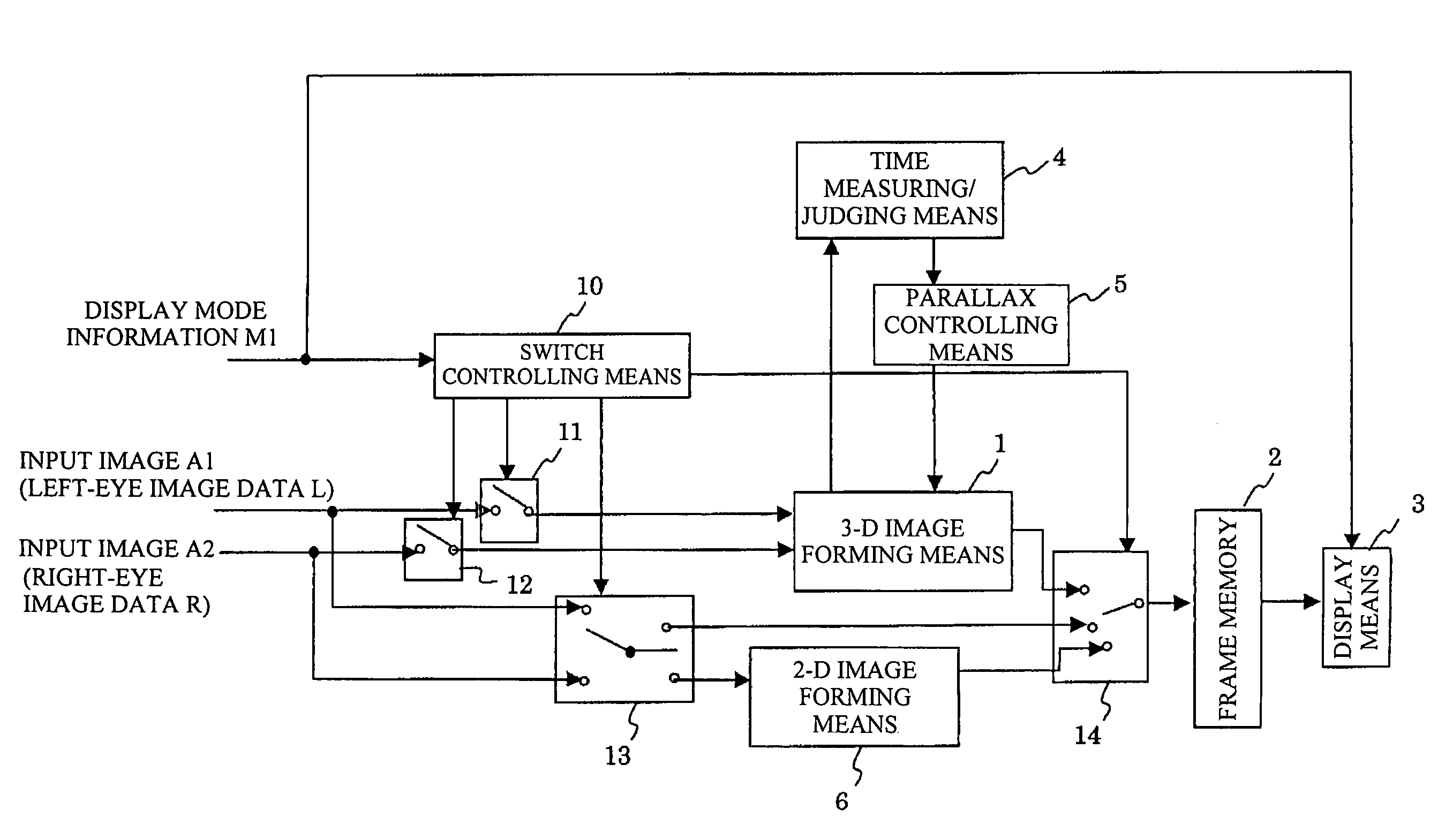
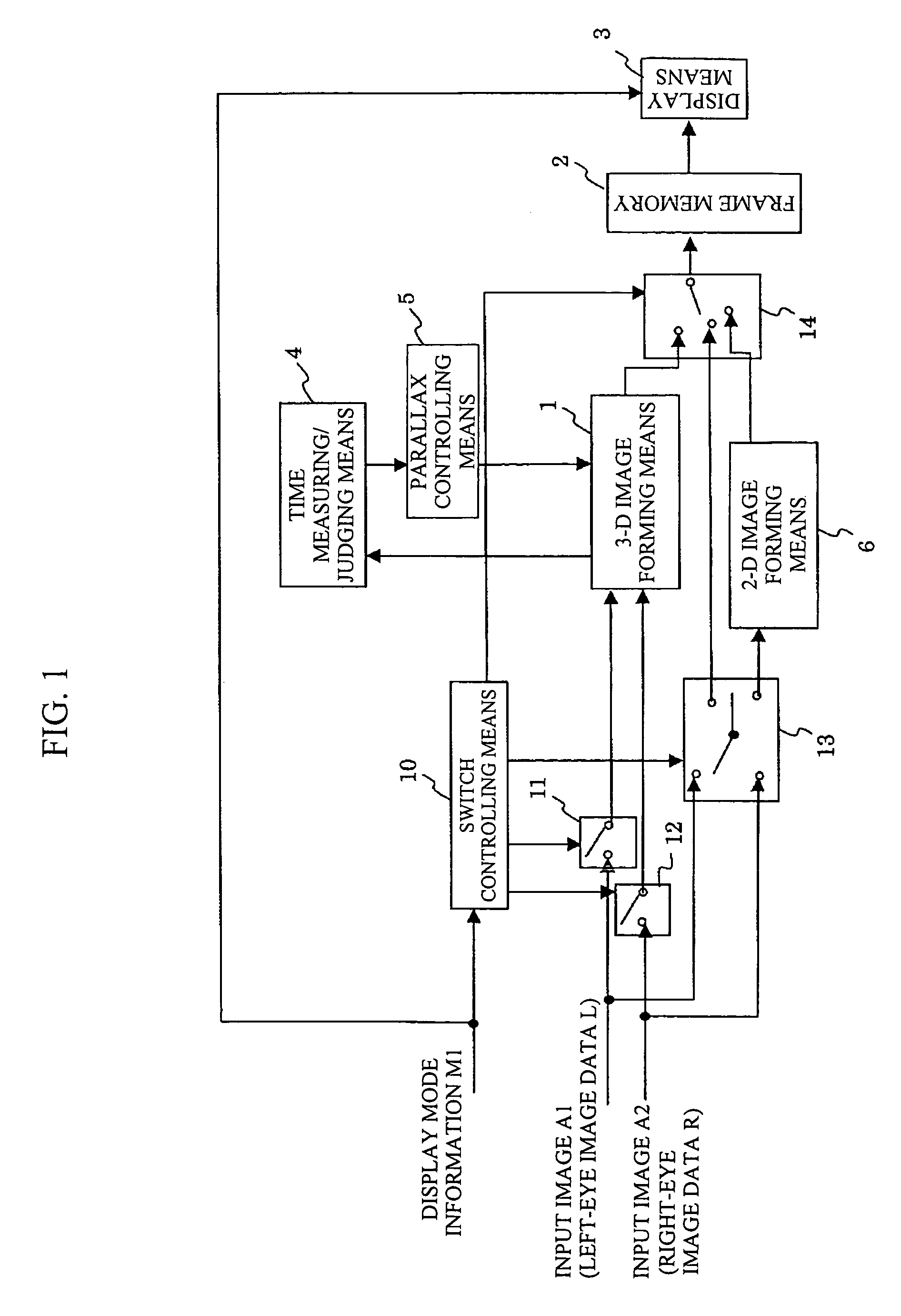
[0085]FIG. 1 shows a block diagram of a 3-D image display unit in the present invention.

[0086]At first, a description will be made for the 3-D image display unit that handles two input images.

[0087]The 3-D image display unit in the first embodiment comprises 3-D image forming means 1 for forming a 3-D image from the images of both right and left eyes, 2-D image forming means 6 for forming a 2-D image from one of the right-eye and left-eye images, switches 11 to 14 for switching among input / output images, a switch controlling means 10 for controlling each of the above switches in accordance with the display information M1 for denoting whether to enable 3-D display or 2-D display with use of the image of each eye (L . . . left eye image data, R: right eye image data), a frame memory 2 for storing each image formed by the 3-D image forming means 1 or 2-D image forming means 6 or input image as is, display means 3 for displaying two images in the frame memory 2 as a 3-D image or 2-D ima...

second embodiment

[0177]Next, the present invention will be described.

[0178]FIG. 14 shows a block diagram of a 3-D image display unit in the second embodiment of the present invention.

[0179]The 3-D image display unit in the second embodiment of the present invention comprises 3-D image forming means 100 for forming a 3-D image with both of inputted right-eye and left-eye images, 2-D image forming means 6 for forming a 2-D image with one of right-eye and left-eye input images, switches 11 to 14 for switching an input / output image to another respectively, switch controlling means 10 for controlling each of those switches 11 to 14 in accordance with the display mode information M1, a frame memory 2 for storing images formed by the 3-D image forming means 100 or 2-D image forming means 6 or input images as are, display means 3 for displaying an image stored in the frame memory 2 as a 3-D or 2-D image in accordance with the display mode information M1, time measuring / judging means 101 for measuring a disp...

third embodiment

[0206]Next, the present invention will be described.

[0207]FIG. 16 shows a block diagram of a 3-D image display unit in the third embodiment of the present invention.

[0208]The 3-D image display unit in the third embodiment of the present invention comprises a switch 201 for selecting one of the display mode information M1 denoting whether to enable 3-D or 2-D image display and the 3-D image display mode information M2 denoting that only 2-D images are displayed so as to be transferred to an input of switch controlling means 200, mode switch controlling means 202 provided with a memory for storing a 3-D image display inhibition flag used to turn on / off the switch 201, 3-D image forming means 203 for forming a 3-D image from both right-eye and left-eye image data, 2-D image forming means 6 for forming a 2-D image from any one of the right-eye and left-eye image data, switches 11 to 14 for switching among input / output image data, switch controlling means 200 for controlling those switch...


PUM


Abstract

Disclosed herein is a 3-D image display unit that can be controlled flexibly to protect the user from eyestrain and operated easily. The 3-D image display unit includes measuring means for measuring a display time of a 3-D image, parallax adjusting means for instructing 3-D image forming means to adjust the parallax of the 3-D image. In the case where the 3-D image display time measured by the measuring means exceeds a predetermined time, the parallax adjusting means instructs the 3-D image forming means to reduce the parallax of the 3-D image to be formed, thereby the display means comes to display a 3-D image having a small parallax. The user can thus be protected from eyestrain.

Description

TECHNICAL FIELD[0001]The present invention relates to a 3-D image display unit for observing electronic images as 3-D images.BACKGROUND ART[0002]Conventionally, each 3-D image display unit, which uses a CRT (Cathode Ray Tube), LCD (Liquid Crystal Display), or the like to display 3-D images, has shifted two images in the eye-width direction to obtain a parallax between those images, then display those shifted images on the screen so as to be recognized by the right and left eyes of the user separately. The user thus comes to recognize a 3-D image configured by those two images.[0003]The patent document 1 (official gazette of Unexamined Published Japanese Patent Application No. 16351 / 1995) discloses a 3-D display game machine that changes over 3-D images to ordinary 2-D images forcibly in the case where a preset 3-D view allowable play time is reached. The patent document 2 (official gazette of Unexamined Published Japanese Patent Application No. 333479 / 1994) discloses an image displa...

Claims


Application Information

Patent Timeline
Patent Type & Authority Patents(United States)
IPC IPC(8): G06K9/00G03B21/60G06T15/00H04N5/66H04N13/122
CPCH04N13/0018H04N13/0033H04N13/0055H04N19/597H04N13/0066H04N13/0454H04N13/0059H04N2213/002H04N13/194H04N13/189H04N13/122H04N13/144H04N13/359H04N13/178H04N13/00
Inventor KITAURA, RYUJIKATATA, HIROYUKINOMURA, TOSHIOITO, NORIOAONO, TOMOKOTAKAHASHI, MAKIHASEGAWA, SHINYAUCHIUMI, TADASHIITO, MOTOHIROTSUJIMOTO, MASATOSHIKUSAO, HIROSHI
Owner SHARP KK
Why Eureka
Try Eureka