Intraoral sensor and X-ray imaging system using the same

a technology of x-ray imaging and sensor, which is applied in the field of intraoral sensor and x-ray imaging system using the same, can solve the problems of reduced convenience, broken transmission cables, and intraoral x-ray imaging, and achieve the effect of ensuring the connection stability between the connectors and the connection terminals

Active Publication Date: 2022-03-22
RAYENCE +1
View PDF21 Cites 0 Cited by
  • Summary
  • Abstract
  • Description
  • Claims
  • Application Information

AI Technical Summary

Benefits of technology

[0011]Accordingly, the convenience of intraoral X-ray imaging can be maximized, and breakage of the transmission cable or connection failure can be fundamentally eliminated, whereby it is possible to effectively improve the limitation of intraoral X-ray imaging due to use of a conventional cable-type intraoral sensor.
[0013]Thereby, the erroneous connection between the connection terminals of the connectors may be reduced, thereby ensuring the connection stability between the connectors.

Problems solved by technology

As described above, the conventional X-ray imaging is problematic in that since a cable-type intraoral sensor is used, there are various limitations in intraoral X-ray imaging, such as reduced convenience, breakage of the transmission cable, or connection failure.

Method used


Image

  • Intraoral sensor and X-ray imaging system using the same
  • Intraoral sensor and X-ray imaging system using the same
  • Intraoral sensor and X-ray imaging system using the same

Examples


first embodiment

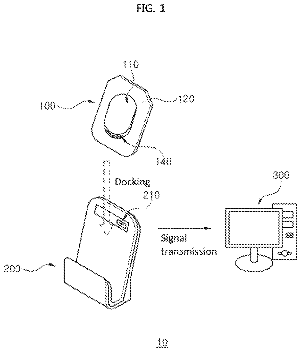
[0027]FIG. 1 is a view schematically showing an X-ray imaging system including an intraoral sensor according to a first embodiment of the present invention.

[0028]An X-ray imaging system 10 according to the first embodiment of the present invention may include an intraoral sensor 100, a docking station 200, and a diagnostic computer 300.

[0029]The computer 300 can display an X-ray image by receiving and processing an image signal generated from the intraoral sensor 100 during X-ray imaging.

[0030]The intraoral sensor 100 is inserted into an oral cavity to perform X-ray detection on teeth and surrounding tissues. To achieve this, the intraoral sensor 100 being inserted into the oral cavity detects X-rays that are generated by an external X-ray generator and transmitted through the teeth and the surrounding tissues, and generates electrical signals according to X-ray intensity by position.

[0031]The intraoral sensor 100 may be a direct type X-ray sensor that directly converts X-rays into ...

second embodiment

[0070]FIG. 5 is a view schematically showing an X-ray imaging system including an intraoral sensor according to a second embodiment of the present invention.

[0071]The first casing 120 of the intraoral sensor 100 according to the embodiment may include a first cover 121, which is a front cover placed forward on the incident surface side of the intraoral sensor 100, and a second cover 122, which is a rear cover placed backward on the opposite side of the incident surface. In this case, the electrical components of the intraoral sensor 100 can be accommodated in a receiving space inside the coupled first and second covers 121 and 122.

[0072]Further, the intraoral sensor 100 may have a shape in which a part or entire of the rear portion thereof protrudes rearward. For example, the second cover 122 may be formed in a protruding shape. As such, in the case where the intraoral sensor 100 is configured in a protruding shape, when the intraoral sensor 100 is viewed in cross section, the side ...


PUM


Abstract

Disclosed are an intraoral sensor and an X-ray imaging system. The intraoral sensor includes a sensor panel, a circuit unit, a memory, a battery, a casing, a first connector, and a power terminal. The X-ray imaging system includes a docking station with the intraoral sensor docked thereto, the docking station configured to provide a second connector connected to the first connector to perform at least one function of receiving the image signal stored in the memory, and charging the battery, or includes a transmission cable detachably connected to the intraoral sensor, and configured to provide a third connector connected to the first connector to transmit the image signal.

Description

CROSS REFERENCE TO RELATED APPLICATION[0001]The present application claims priority to Korean Patent Application No. 10-2017-0032536, filed Mar. 15, 2017, and No. 10-2017-0121218, filed Sep. 20, 2017, the entire contents of which is incorporated herein for all purposes by this reference.BACKGROUND OF THE INVENTIONField of the Invention[0002]The present invention relates to an intraoral sensor and an X-ray imaging system using the same.Description of the Related Art[0003]Recently, digital intraoral sensors have been used to obtain X-ray images of teeth and surrounding tissues in an oral cavity.[0004]In a conventional X-ray imaging system using an intraoral sensor, X-ray imaging is performed using a cable-type intraoral sensor to which a transmission cable is fixed and connected, and an image signal generated from the intraoral sensor by X-ray imaging is transmitted to a diagnostic computer via the transmission cable.[0005]As described above, the conventional X-ray imaging is problema...

Claims


Application Information

Patent Timeline
Patent Type & Authority Patents(United States)
IPC IPC(8): A61B6/14G01T1/208G01T7/00G01T1/24H04N5/32
CPCA61B6/145G01T1/208G01T1/244G01T7/00H04N5/32
Inventor KIM, TAE WOOJEON, YU SUNGKIM, YEONG KYUNKIM, JUNG DO
Owner RAYENCE
Why Eureka
Try Eureka