Pneumatic cleaner

a technology of pneumatic cleaners and cleaners, applied in the direction of auxillary pretreatment, cleaning filter means, separation processes, etc., can solve the problems of large power units, inability to carry, bulky units, etc., and achieve the effect of quiet operation, small size and configuration, and large power units

Active Publication Date: 2010-05-25
SHOP VAC
View PDF37 Cites 19 Cited by
  • Summary
  • Abstract
  • Description
  • Claims
  • Application Information

AI Technical Summary

Benefits of technology

[0005]The applicants have a developed an arrangement that is relatively manageable in size and configuration yet can still provide relatively quiet, powerful operation.

Problems solved by technology

Generally, powerful units are large, bulky, and inherently noisy.
One problem with backpack vacuums is that the size and depth of a quiet, powerful unit can make the unit awkward to carry.

Method used


Image

  • Pneumatic cleaner
  • Pneumatic cleaner
  • Pneumatic cleaner

Examples


Embodiment Construction

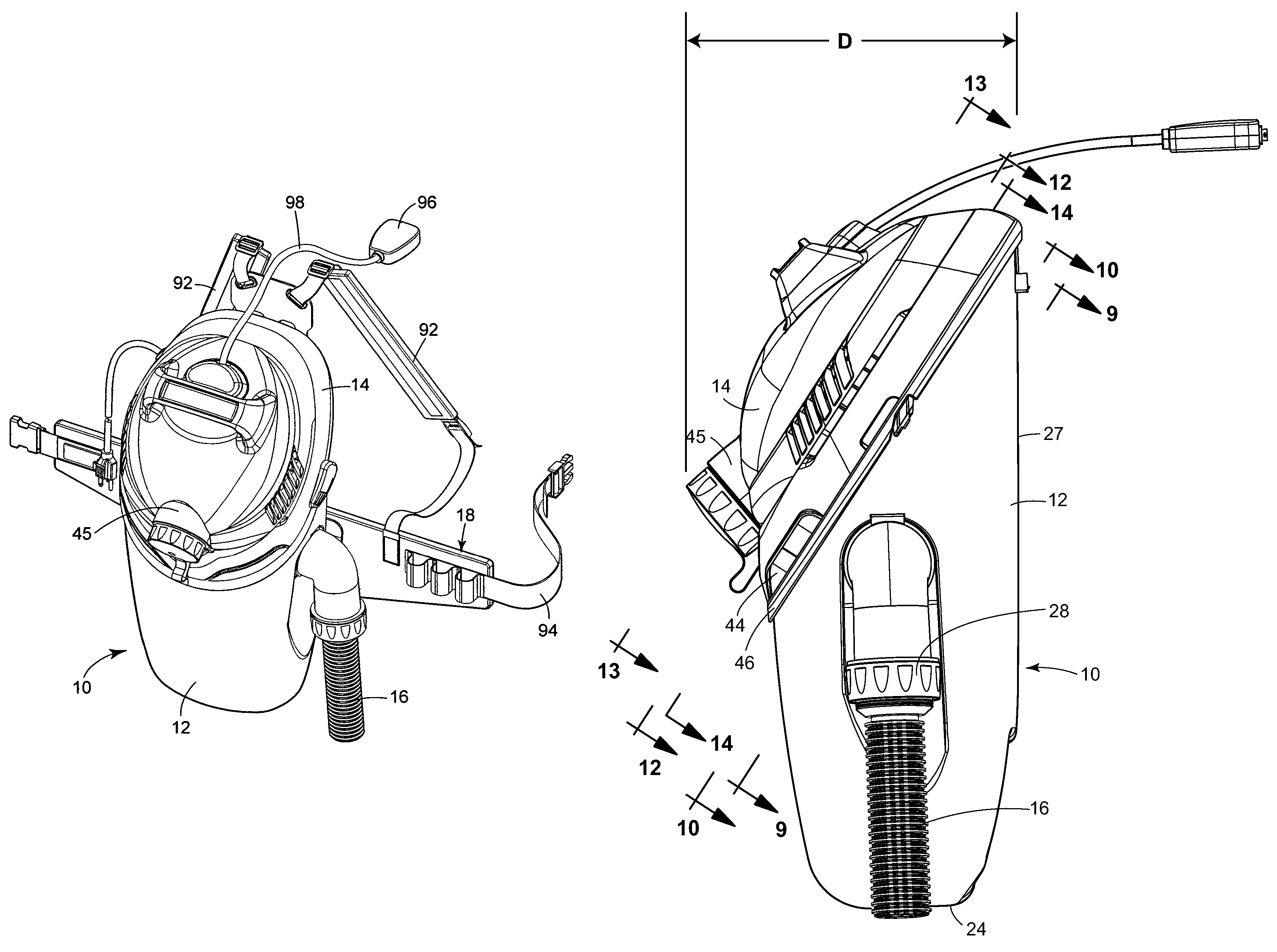
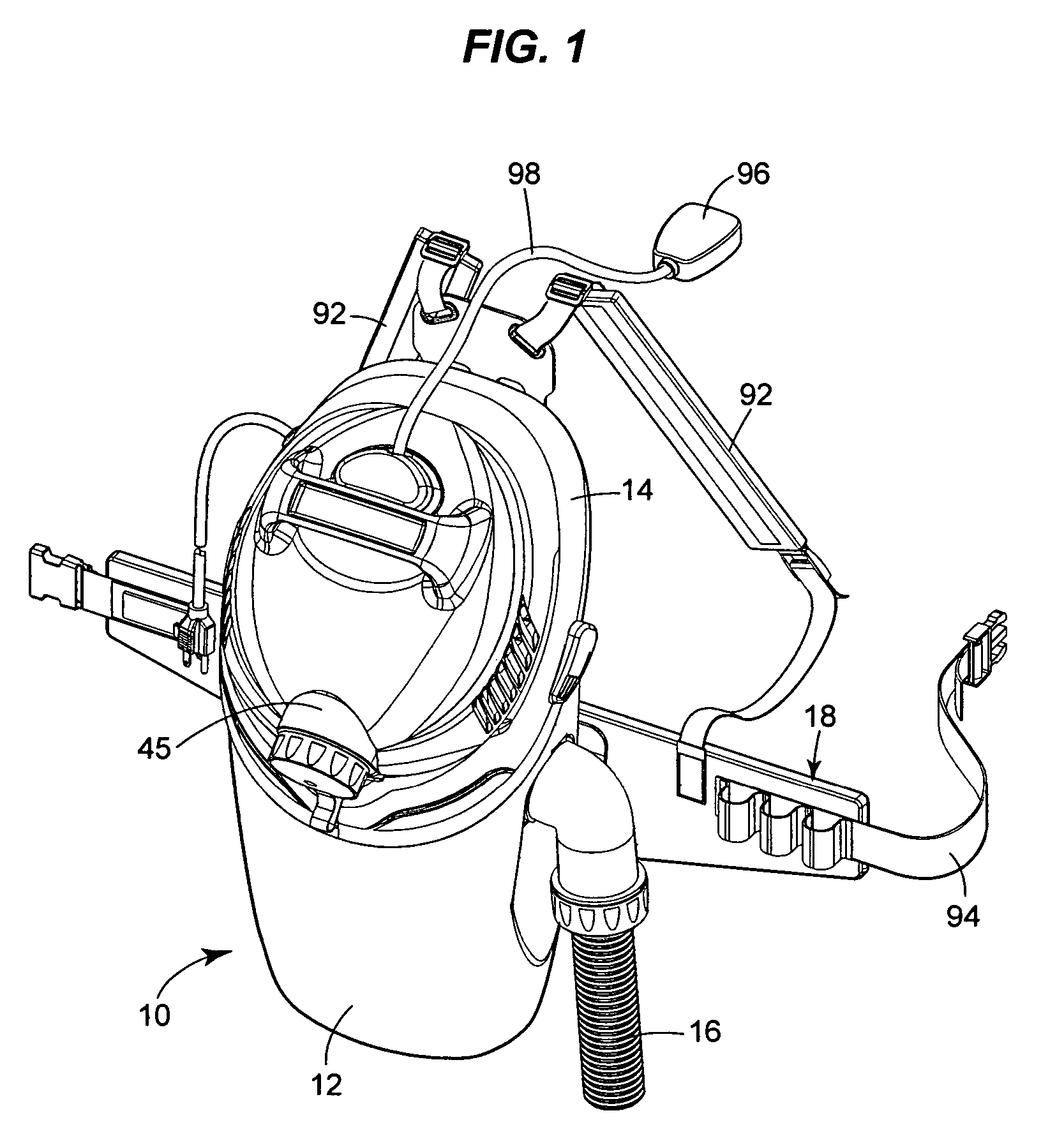
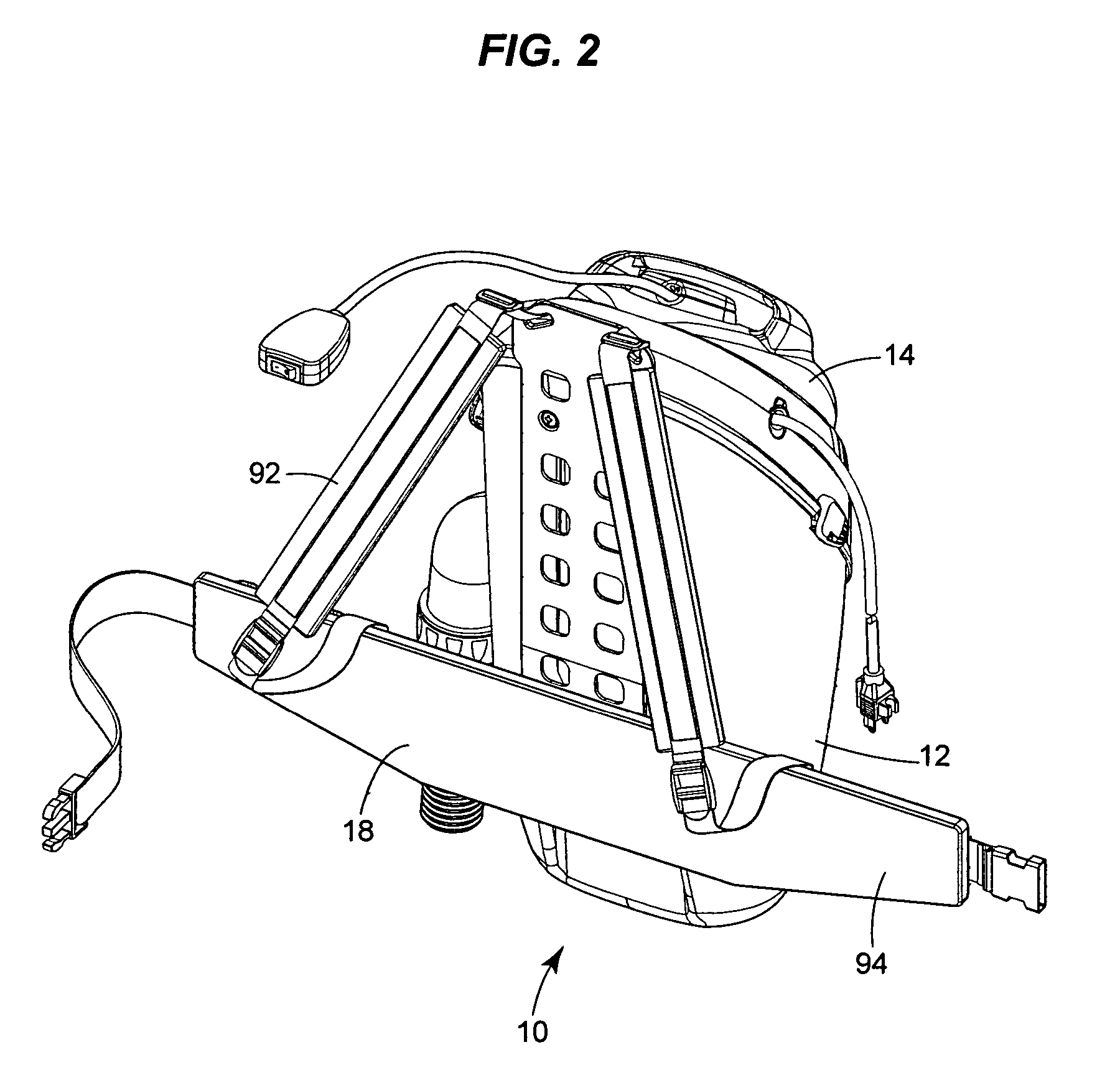
[0022]FIGS. 1-6 depict one form of pneumatic cleaner that can be built using the invention. The illustrated cleaner is a vacuum 10. The vacuum has a tank 12, a lid assembly 14, a hose 16, and a harness 18 that allows the vacuum to be carried as a backpack.

[0023]The Tank

[0024]The illustrated tank 12 is a dirt tank with tanks walls 22 (best seen in FIG. 7) that rise from a tank bottom 24 around a tank axis 26 that parallels the front of the tank (the part of the tank that, in use, forms an unhinged panel 27 toward the user's back). The illustrated tank axis 26 (FIG. 7) is vertical, but it could also be angled with respect to the vertical. The upper edge 30 of the tank lies on a plane 31 that is canted at an angle of approximately 35 degrees with respect to the tank axis 26. Preferably, the plane 31 is canted at an angle between 25° and 75° degrees with respect to the tank axis 26 and / or to the vertical. In cross section (as can be discerned from FIG. 6), the illustrated dirt tank 12 h...


PUM

PropertyMeasurementUnit
depthaaaaaaaaaa
depthaaaaaaaaaa
distanceaaaaaaaaaa

Abstract

A pneumatic cleaner that can be worn as a backpack has a reduced unit overall depth. The impeller shaft is mounted at an acute angle. Tangential airflow chambers are disposed around the motor assembly and substantially surround the impeller. Two of the airflow chambers extend substantially the entire overall unit depth, and have lateral lengths that exceed the overall unit depth.

Description

BACKGROUND OF THE INVENTION[0001]The present invention relates generally to pneumatic cleaners (vacuums, blowers, etc.), and more particularly to vacuum cleaners that can be worn as a backpack.[0002]Over the years, vacuum cleaners and blowers have been adapted for many different uses. Generally, powerful units are large, bulky, and inherently noisy. Interior ducting is commonly used to dampen the noise produced by a motor and internal airflow. This ducting further increases the bulk of a unit.[0003]Portability is a common concern. To improve portability, some vacuums or blowers (including those seen in U.S. Pat. Nos. 6,647,586; 6,115,879; 5,040,263; and 4,223,419) have been designed with a strap that can be slung over a user's shoulder. Others (including those seen in U.S. Pat. Nos. 6,473,933; 6,151,749; 6,066,211; and 4,944,065) have been designed with waist belts. Still others (including those seen in U.S. Pat. Nos. 6,857,163; 6,568,026; 6,553,610; 6,431,024; 6,295,692; 6,073,301;...

Claims


Application Information

Patent Timeline
Patent Type & Authority Patents(United States)
IPC IPC(8): A47L5/36
CPCA47L5/14A47L9/0081A47L5/36
Inventor CREVLING, JR., ROBERT L.SEASHOLTZ, CRAIG A.KEPNER, MATTHEW S.
Owner SHOP VAC
Why Eureka
Try Eureka