
Self-contained micromechanical ventilator

a micromechanical ventilator and self-contained technology, applied in mechanical devices, valves, respirators, etc., can solve the problems of inconvenient transportation, heavy air/oxygen, heavy, etc., and achieve the effect of reducing the number of patients

Inactive Publication Date: 2010-05-25
AUTOMEDX
View PDF2 Cites 108 Cited by
  • Summary
  • Abstract
  • Description
  • Claims
  • Application Information

AI Technical Summary

Benefits of technology

[0011]It is another objective of the present invention to provide a portable ventilator wherein the pneumatic subsystem includes two dual head compressor for increased air output.
[0013]It is another objective of the present invention to provide a portable ventilator that is a disposable one-use device having an indefinite shelf life.
[0015]It is another objective of the present invention to provide a portable ventilator wherein the pneumatic subsystem includes one dual head compressor for increased air output and a means for relieving air manifold pressure with a single head compressor, thereby eliminating the need for an accumulator.

Problems solved by technology

However, definitive medical attention is often limited, because of the lack of necessary equipment.
While state of the art medical equipment can be found in medical facilities, such is not the case in emergency situations or military applications.
They are heavy, cumbersome and ill suited for portable applications.
These tanks air / oxygen are heavy, cumbersome, and unsuitable for transport.
Prior-art ventilators also require large power sources, making them even less suitable for quick, on-site use.
However, these devices lack the means by which they can be quickly facilitated in emergency situations where there are no stationary sources of power.
Secondly, most of these devices depend on canister-style oxygen sources, which are cumbersome, and lessen the ability of the ventilators to be truly portable.
Thirdly, the prior art ventilators do not provide breathing circuits that can be continuously used in the absence of stationary power sources.

Method used


Image

  • Self-contained micromechanical ventilator
  • Self-contained micromechanical ventilator
  • Self-contained micromechanical ventilator

Examples


example 1

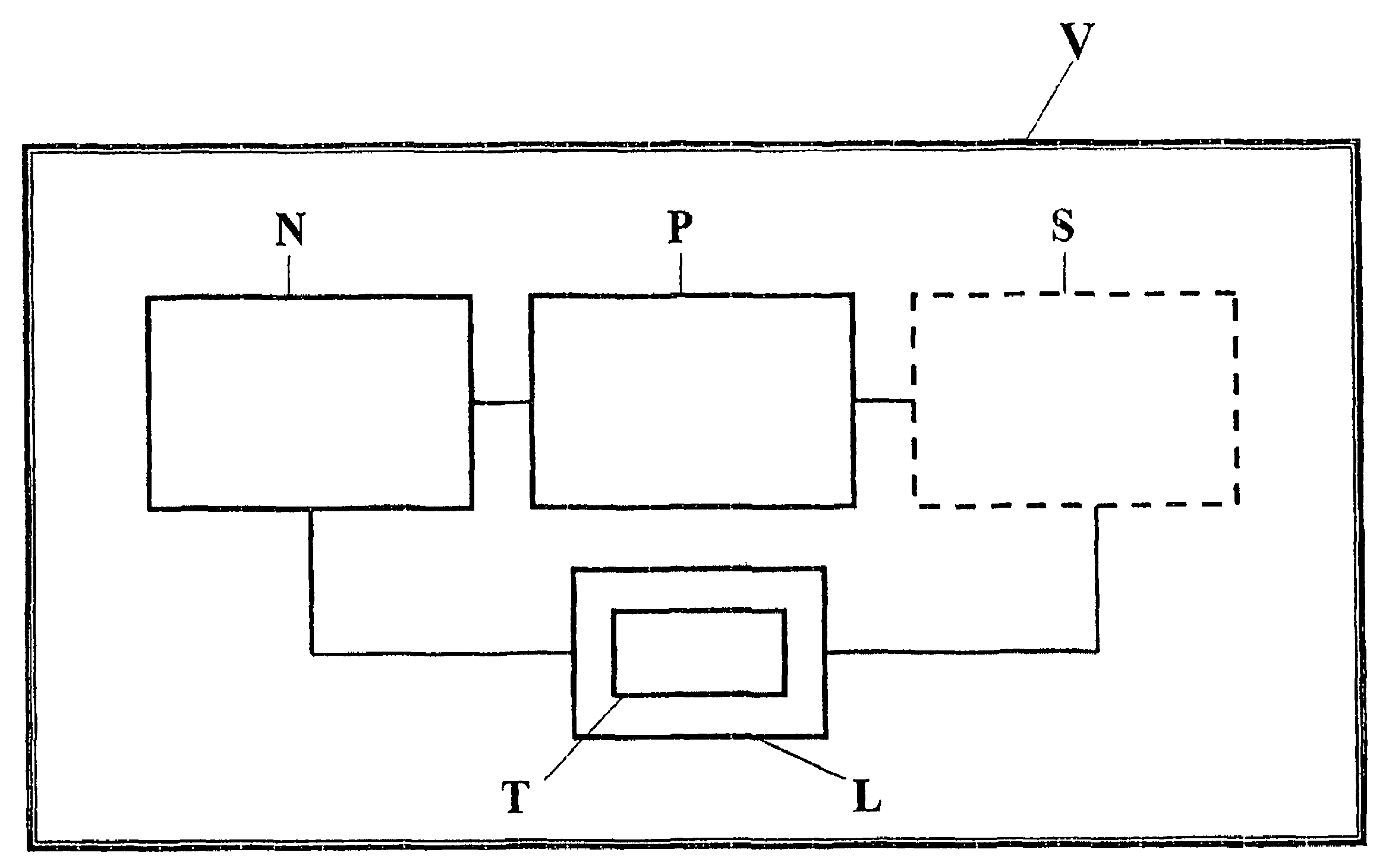
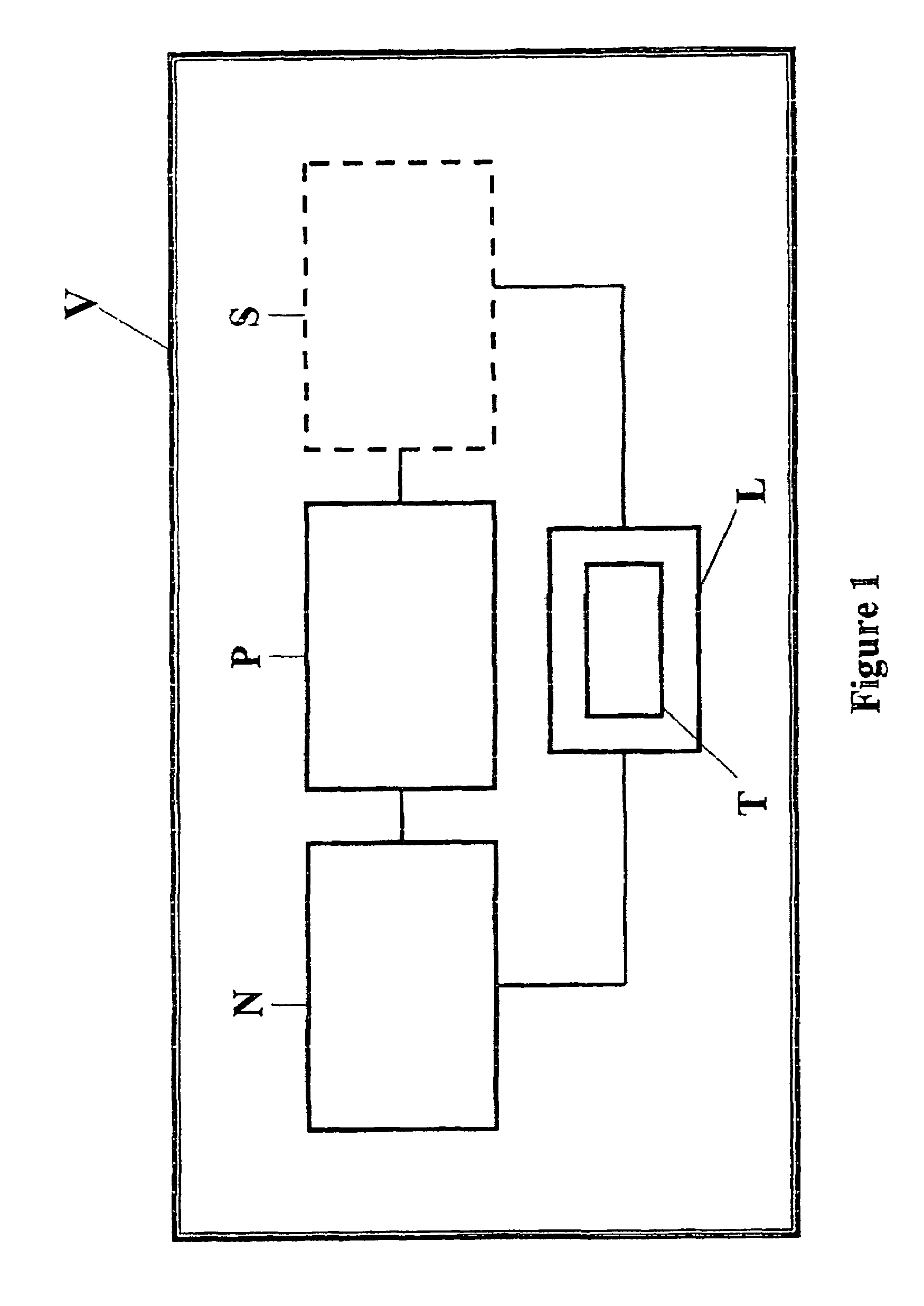
[0063]The Sekos 2 and 3 ventilators were tested. All tidal volumes, respiratory rates and other parameters were within ±10% of the settings existing on the ventilator V.

[0064]

PERFORMANCEPARAMETERSEKOS 2SEKOS 3APPROX. WEIGHT (lb012APPROX. SIZE (in.)10.75 W × 9.75 D × 7 H5.7 W × 11.5 D × 3.5 HPHYSICAL VOLUME (in3)733230BATTERY TYPE / SIZE3.4 Ah lead acid1.3 Ah lead acidOPERATING LIFE (h)1.5-30.3-1COMPRESSORS22CONTROLLABLE I:E RATIONoNoRESP. RATE6-3010 OR 20 ONLYADJUSTMENT (bpm)TIDAL VOLUME (ml)200-1200300, 900, OR 1200MAX MINUTE VOLUME20 (NOT YET TESTED)20 (NOT YET TESTED)(L / m)INSPIRATORY FLOWNoNoMEASUREMENTEXPIRATORY FLOWYesYesMEASUREMENT

[0065]The portable ventilators tested above, have been shown to be superior in performance to traditional “ambu-bags”. These and other portable ventilators having the features discussed above are within the scope of this invention.

[0066]The present invention includes a preferred embodiment as shown in FIG. 6. The portable ventilator V2, as shown in FIG...

example 2

[0069]For an equivalent tidal volume output:[0070]Dual Head Compressor: weight—14.2 oz, size—28.9 cubic inches.[0071]2 Single Head Compressors: weight—20.4 oz, size—32.0 cubic inches.

[0072]Dual-head compressors draw in outside air and increase pressure within, to allow for the proper tidal volumes to be pushed through a small amount of space. Using the ideal gas law PV=nRT, where (P)=pressure, (V)=volume, (n)=number of molecules, (R)=gas law constant, and (T)=temperature, the values nRT must remain constant when dual head compressor 101 is operational. Thus, as necessitated by the proper operation of ventilator V2, obtaining particular volumes (V) of air from the environment into a small, fixed volume of the ventilator V2, requires that the pressure (P) of the air a must be increased to keep nRT the same. The increased pressure of air a forces the air a through the ventilator V2 into the lungs of the patient H. This is due to the tendencies of fluids, here the compressed air a, to f...


PUM


Abstract

The portable ventilator of the present invention provides a hands-free ventilatory support device in critical care, emergency, and resource-limited environments. The portable ventilator utilizes ambient air and includes a two dual head compressor system to provide a consistent air supply to the patient. The ventilator device is battery operated and is capable of providing up to 60 minutes of care. In a preferred embodiment, the portable ventilator of the present invention also includes a pneumatic subsystem, a control subsystem, a power subsystem and an alarm subsystem. The portable ventilator of the preferred embodiment includes a dual head and single head compressor system that operates alternatively, to provide a consistent and continuous inhalation and exhalation cycle. A portable ventilator of a second preferred embodiment includes a sole dual-head compressor that operates to provide a consistent and continuous inhalation and exhalation cycle.

Description

[0001]This application is a continuation-in-part of application Ser. No. 10 / 228,166, filed Aug. 26, 2002 now U.S. Pat. No. 7,080,646 and a continuation-in-part of application Ser. No. 10 / 787,522, filed Feb. 26, 2004 now U.S. Pat. No. 7,320,321.BACKGROUND OF THE INVENTION[0002]Immediate medical care can save the lives of countless accident victims and military personnel. In the emergency medical services arena, there has long been an emphasis on the golden hour during which a patient must receive definitive medical attention. However, definitive medical attention is often limited, because of the lack of necessary equipment. While state of the art medical equipment can be found in medical facilities, such is not the case in emergency situations or military applications. This is particularly true in the area of ventilators.[0003]Inspiration-only ventilators are known and widely used in hospital settings as they provide useful breathing circuits while minimizing the amount of oxygen uti...

Claims


Application Information

Patent Timeline
Patent Type & Authority Patents(United States)
IPC IPC(8): A61M16/00
CPCA61M16/00A61M16/0051A61M16/0063A62B99/00A61M2016/0021A61M2016/0027A61M2016/0036A61M2205/581A61M2205/583A61M2205/8206A61M2230/432A61M2205/16A61M16/0009A61M16/107A61M2016/0413A61M16/0858A61M16/022
Inventor URIAS, ADRIANPRANGER, LOLAND A.WIESMANN, WILLIAM P.SMITH, EARL
Owner AUTOMEDX
Learn More