Method and apparatus for autonegotiation between network devices

a network device and autonegotiation technology, applied in the field of autonegotiation controllers, can solve the problems of requiring an external power supply and being costly

Active Publication Date: 2010-05-25
MARVELL ASIA PTE LTD
View PDF32 Cites 6 Cited by
  • Summary
  • Abstract
  • Description
  • Claims
  • Application Information

AI Technical Summary

Problems solved by technology

This methodology suffers from a number of drawbacks, including requiring an external power supply, which can be costly.

Method used


Image

  • Method and apparatus for autonegotiation between network devices
  • Method and apparatus for autonegotiation between network devices
  • Method and apparatus for autonegotiation between network devices

Examples


first embodiment

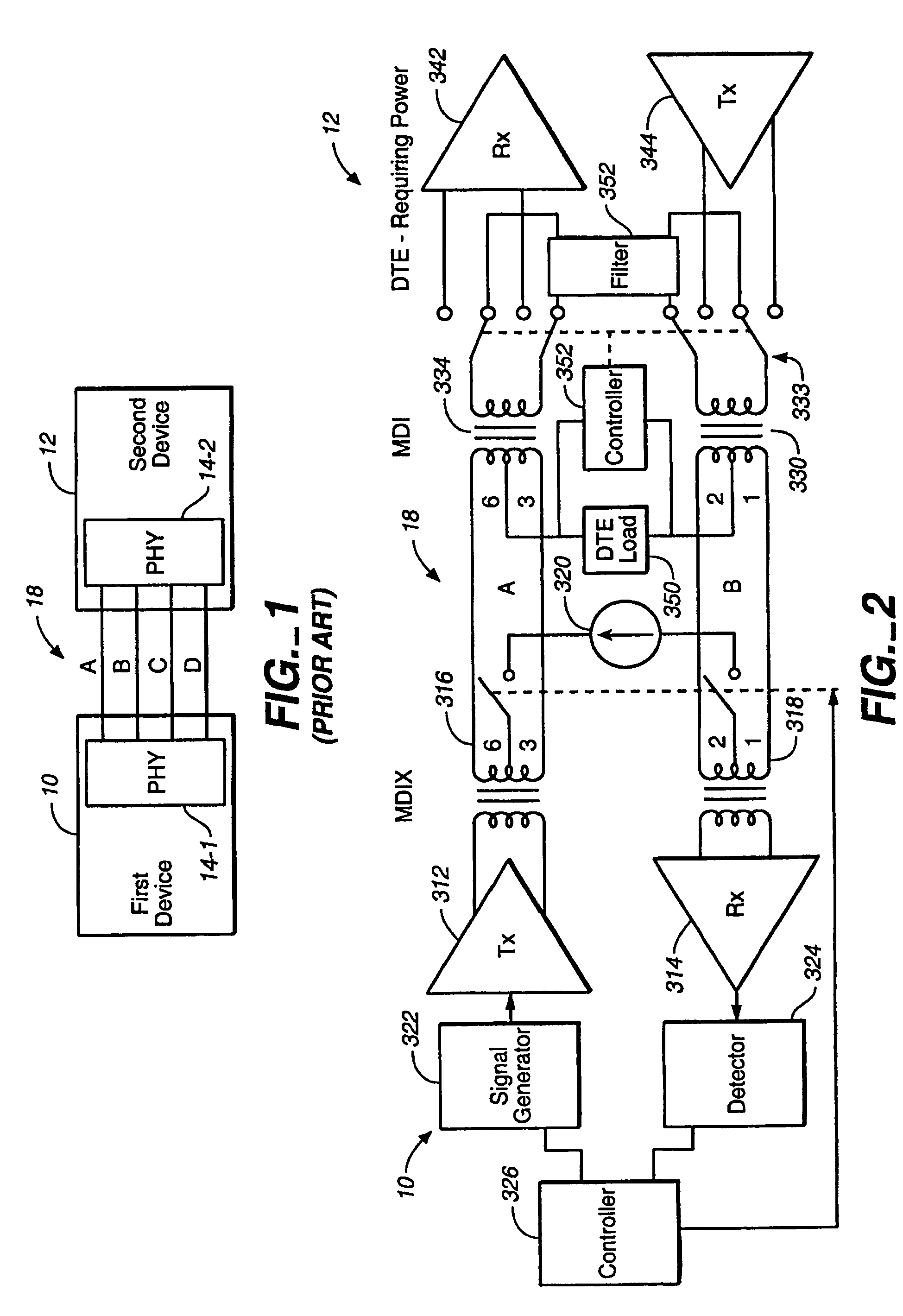
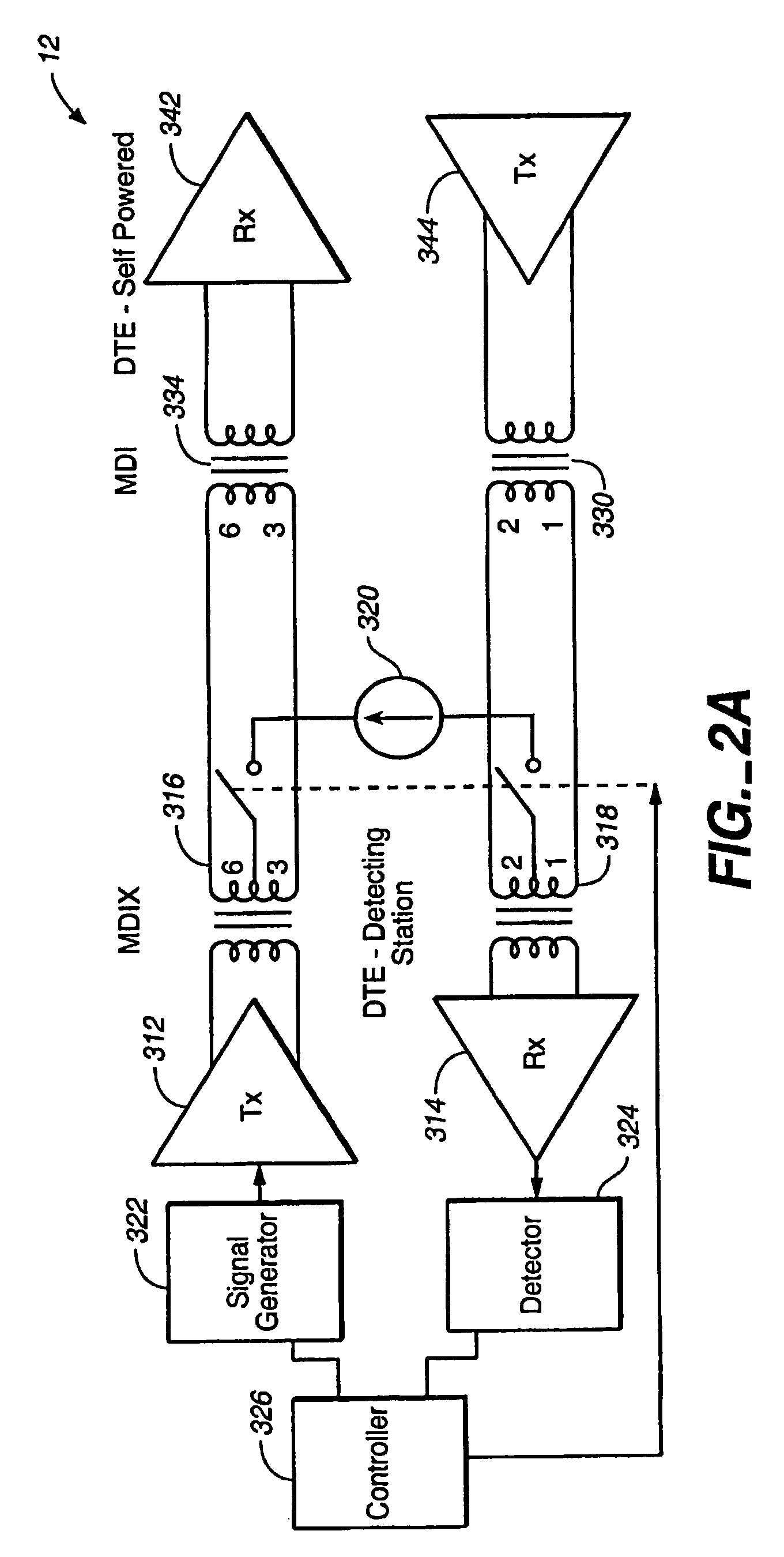
[0082]The following is a detailed description for detecting whether the connected network device 12 (12′) is a cable-powered DTE device or self-powered DTE device. In network device 10, signal generator 322 generates test signals for transmission by transmitter 312 over pair A of data cable 18, the test signal returns through filter 18 and pair B of data cable 18, receiver 314 to detector 324. If the network device 12′ is a self-powered DTE device, as shown in FIG. 2B, or if there is an open circuit, detector 324 does not detect a return signal. As a result power is not supplied by network device 10 to network device 12′ over data cable 18.

[0083]Referring to FIG. 3A, an exemplary test signal generated by signal generator 322 comprising plural pulses is illustrated. An initial pulse having a magnitude of −1 volt is applied for 752 ns followed by, positive pulses (1 volt) having a width of about 152 ns, negative (−1 volt) pulses having a width of approximately 72 ns and ending with a ...

second embodiment

[0092]Referring to FIG. 3B, an exemplary test signal generated by signal generator 322 comprising plural pulses in accordance with the second embodiment is illustrated. The width of each positive pulse is about 150 ns, and the width of each negative pulse is approximately 70 ns. Successive test signals are spaced by at least 156 ms. When a cable powered DTE requiring power is not already being supplied with power, signal generator 322 generates test signals for transmission by transmitter 312 over pair A of data cable 18. The test signal returns through filter 18 and pair B of data cable 18, receiver 314 to detector 324. If the network device 12′ is a self-powered DTE device or there is an open circuit, as shown in FIG. 2B, detector 324 does not detect a return signal. As a result power is not supplied by network device 10 to network device 12′ over data cable 18.

[0093]FIG. 4B illustrates the test signal received by detector 324 when the length of the data cable is approximately zer...


PUM


Abstract

A physical layer device comprises a transmitter of a first network device that transmits an autonegotiation signal to a second network device. A receiver of the first network device receives a received signal from the second network device. An autonegotiation controller autonegotiates link parameters for a link between the first network device and the second network device, monitors autonegotiation pulses in the autonegotiation signal relative to autonegotiation pulses in the received signal received during a window, and selectively blinds autonegotiation based on the monitoring.

Description

CROSS REFERENCE TO RELATED APPLICATIONS[0001]This application is a continuation of U.S. patent application Ser. No. 10 / 099,050, filed Mar. 15, 2002 (now U.S. Pat. No. 7,161,911, issued Jan. 9, 2007), which application claims priority under 35 U.S.C. 119(e) to U.S. provisional Application Ser. No. 60 / 280,735, entitled “Apparatus For DTE Power Via MDI and Method Thereof”, filed Apr. 3, 2001, the contents of which are incorporated by reference herein.BACKGROUND OF THE INVENTION[0002]1. Field of the Invention[0003]The present invention relates to autonegotiation controllers within the physical layer of devices that are connected to an Ethernet network. More particularly, the present invention is directed to an autonegotiation controller which detects returned pulse while having a good detection margins over a long cable and to detect a faulty filter connected thereto.[0004]2. Description of the Related Art[0005]FIG. 1 illustrates a network device 10 in communication with another network...

Claims


Application Information

Patent Timeline
Patent Type & Authority Patents(United States)
IPC IPC(8): H04B1/44
CPCH04B1/44
Inventor FANG, CALVINCHENG, YILO, WILLIAM
Owner MARVELL ASIA PTE LTD
Why Eureka
Try Eureka