Combined steering angle and torque sensor

a technology of torque sensor and steering angle, which is applied in the direction of instruments, galvano-magnetic hall-effect devices, transportation and packaging, etc., can solve the problems of large overall space required, the range of steering angle also determined by the required accuracy, and the limited range of steering angl

Inactive Publication Date: 2010-06-01
ZF FRIEDRICHSHAFEN AG
View PDF41 Cites 35 Cited by
  • Summary
  • Abstract
  • Description
  • Claims
  • Application Information

AI Technical Summary

Problems solved by technology

In many multiturn sensors the steering angle range is also determined by the required accuracy and is often limited.
Frequently a larger amount of space is required overall.

Method used


Image

  • Combined steering angle and torque sensor
  • Combined steering angle and torque sensor
  • Combined steering angle and torque sensor

Examples


Embodiment Construction

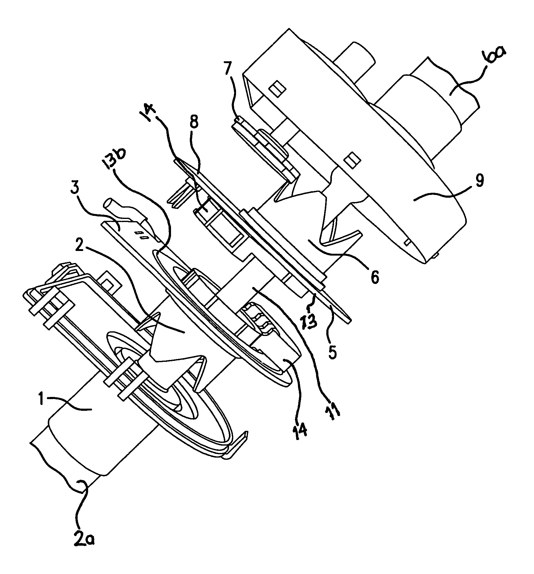
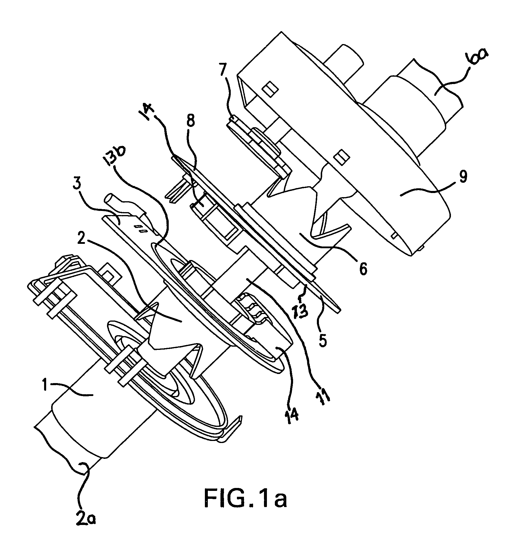
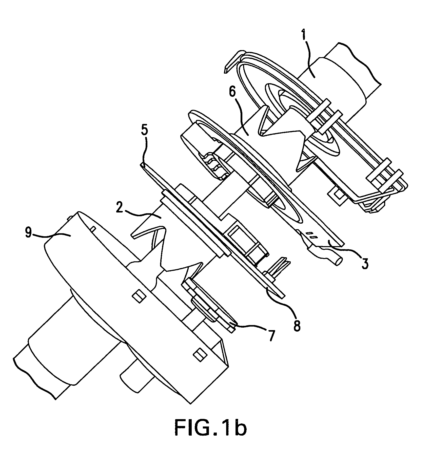
[0020]In FIG. 1a a housing 9, including a bottom and a housing cover 1, is pulled apart in the axial direction of the steering column 2a, 6a so that an exemplary embodiment of the inventive combination sensor can be seen. FIG. 8 depicts the installation site for this housing 1, 9 on the steering column 2a, 6a in greater detail. The steering column is divided by an input shaft 2a and an output shaft 6a. A worm wheel that belongs to the gear housing 2a is seated on the output shaft 6a. Adjacent thereto is the abutment 12 of the input shaft 2a and of the output shaft 6a, which passes through the sensor housing 1, 9. In accordance with FIG. 1b, the multiturn sensor 7 can also be arranged on the input shaft 2a in order to save space.

[0021]The axial section of the input shaft 2a, the output shaft 6a, and an interiorly situated torsion bar 11 can be seen in FIG. 6. The elastic rotation of the torsion bar 11 determines the relative angle difference for the shaft ends at the abutment 12 as a...


PUM

PropertyMeasurementUnit
angleaaaaaaaaaa
steering angleaaaaaaaaaa

Abstract

A combined steering angle and torque sensor that inductively and with eddy current damping generates two absolute angle measurement signals over an angle range of 360 degrees including a first damping rotor being disposed on an end of an input shaft of steering column divided by a torsion element; a second damping rotor being disposed on an end of an output shaft of the steering column; at least one carrier being fixed to a housing of the steering column and through which the steering column passes at a right angle, the at least one carrier being fitted with flat coils in a complete angle range; and at least one passive actuating element, without periodically repeated structures, being borne on each of said first and second damping rotors, the actuating elements being in two different locations of said angle range acting on the flat coils of the at least one carrier.

Description

BACKGROUND OF THE INVENTION[0001]The invention relates to a combined steering angle and torque sensor that inductively and with eddy current damping generates two absolute angle measurement signals over an angle range of 360 degrees.[0002]For such measurements the steering column is normally divided by a torsion element at an abutment. The input shaft faces the steering wheel and bears a first actuating element in the vicinity of the twisted abutment. The output shaft of the steering column is associated with the steering gear and bears a second actuating element in the vicinity of the twisted abutment.[0003]In this technical context, known in the prior art are (i) an inductive measurement technique by means of eddy current damping, (ii) measurement planes perpendicular to the axis of rotation, and (iii) two annular disk-shaped electrical damping members that are attached to the steering column on both sides of the torsion element; see the prior art in accordance with DE 29 51 148 C...

Claims


Application Information

Patent Timeline
Patent Type & Authority Patents(United States)
IPC IPC(8): G01L3/00G01B7/30
CPCB62D6/10B62D15/0215G01L3/104G01D5/202B62D15/0245
Inventor HOELLER, REINHOLDRASCHKE, DIRKWALLNER, HERBERTGOETZ, HANS-LUDWIG
Owner ZF FRIEDRICHSHAFEN AG
Why Eureka
Try Eureka