Method and apparatus for recording and reproducing signal on and from optical information recording medium

a technology of optical information and recording medium, applied in the field of method and apparatus for recording and reproducing signals on and from optical information recording mediums, can solve the problems of determining the optimum recording power, power, optimum erasing power, and the optimum bias power (the optimum bottom power) of a laser beam for a dvd-rw having multiple recording layers, and achieve the effect of accurately deciding the optimum erasing power of a laser beam applied

Inactive Publication Date: 2010-06-01
JVC KENWOOD CORP
View PDF5 Cites 7 Cited by
  • Summary
  • Abstract
  • Description
  • Claims
  • Application Information

AI Technical Summary

Benefits of technology

[0011]It is a first object of this invention to provide an apparatus for recording and reproducing a signal on and from an optical information recording medium with multiple recording layers which can accurately decide the optimum erasing power of a laser beam applied to the recording medium.
[0012]It is a second object of this invention to provide a method of recording and reproducing a signal on and from an optical information recording medium with multiple recording layers which can accurately decide the optimum erasing power of a laser beam applied to the recording medium.
[0014]It is a fourth object of this invention to provide a computer program for recording and reproducing a signal on and from an optical information recording medium with multiple recording layers which can accurately decide the optimum erasing power of a laser beam applied to the recording medium.

Problems solved by technology

In general, deciding the optimum recording power (the optimum writing power), the optimum erasing power, and the optimum bias power (the optimum bottom power) of a laser beam for a DVD-RW having multiple recording layers is more difficult than deciding those for a DVD-RW having only a single recording layer.

Method used


Image

  • Method and apparatus for recording and reproducing signal on and from optical information recording medium
  • Method and apparatus for recording and reproducing signal on and from optical information recording medium
  • Method and apparatus for recording and reproducing signal on and from optical information recording medium

Examples


first embodiment

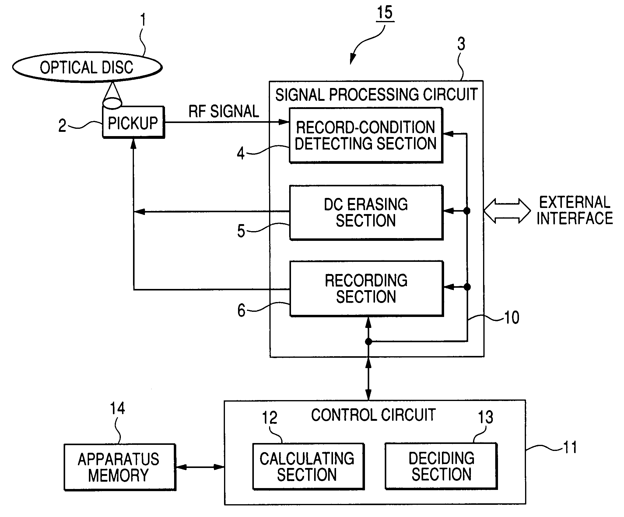
[0093]FIG. 7 shows an optical-disc drive apparatus 15, that is, an apparatus 15 for recording and reproducing a signal on and from an optical disc 1, in a first embodiment of this invention. The optical-disc drive apparatus 15 is designed to perform a novel OPC (optimum power control) procedure and the recording and reproduction of data on and from the optical disc 1. The optical-disc drive apparatus 15 may further perform a general OPC procedure identical or similar to prior-art one.

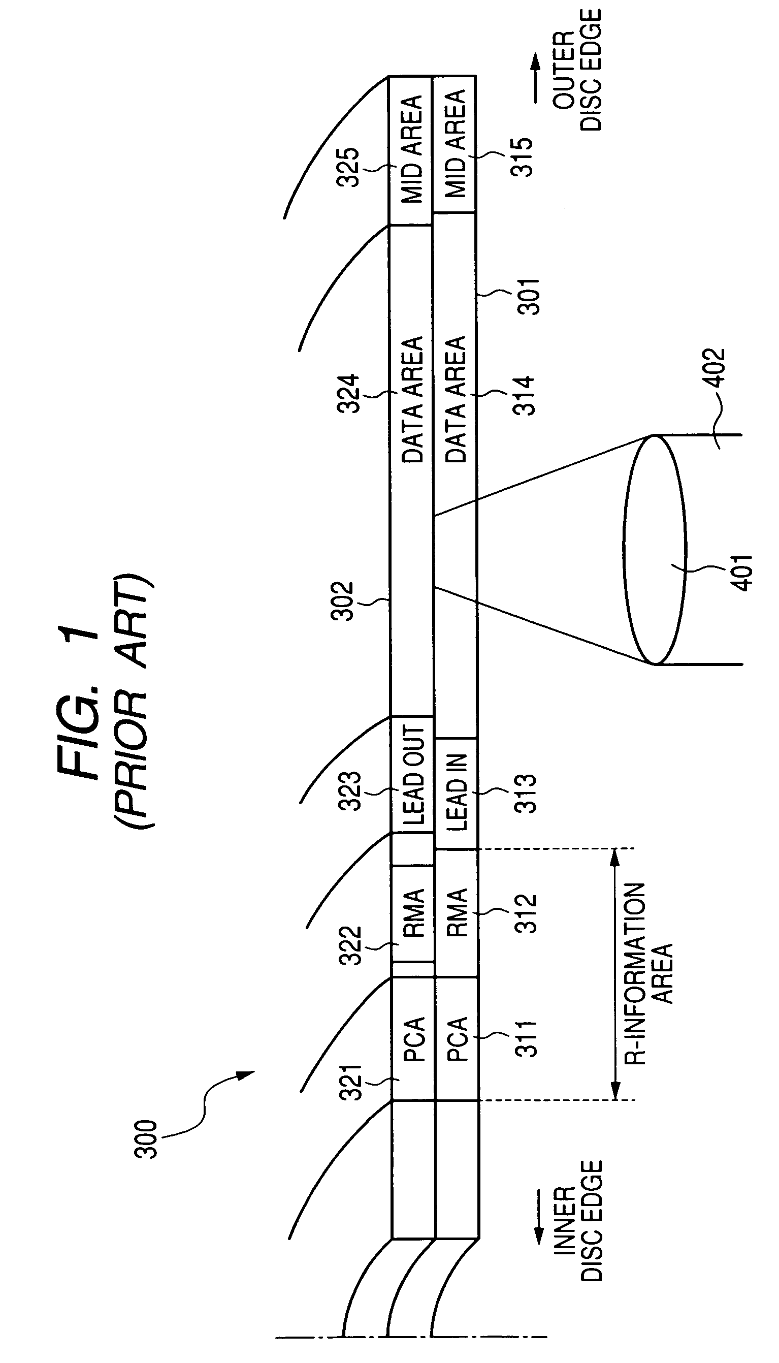
[0094]The optical disc 1 is of a rewritable type. The optical disc 1 has a laminate of recording layers as viewed in an axial direction of the disc, that is, an axial direction of a laser beam scanning the disc. Preferably, the optical disc 1 is of a two-layer single-sided type identical or similar to that in FIG. 1. The optical disc 1 is, for example, a DVD-RW. It should be noted that the optical disc 1 may have only a single recording layer.

[0095]The optical-disc drive apparatus 15 includes an optical...

second embodiment

[0157]A second embodiment of this invention is similar to the first embodiment thereof except for design changes mentioned hereafter.

[0158]As the test-signal recorded portion of the optical disc 1 is exposed to DC erasure using the forward laser beam having a DC erasing power which increases stepwise, short recorded marks are erased first and long recorded marks are erased second and the reproduced RF signal amplitude decreases. Thus, the long recorded marks are higher than the short ones in remaining degree. The detection of peak levels and bottom levels of a reproduced RF signal causes the detection of the amplitude of corresponding recorded marks. Therefore, the detected amplitude of the recorded marks mainly reflects the remaining degree concerning long recorded marks.

[0159]To attain a high detection accuracy, the second embodiment of this invention uses a test signal formed by only a longest mark signal (a 14T signal in the case of an 8 / 16-modulation-result signal).

[0160]Test s...

third embodiment

[0164]A third embodiment of this invention is similar to the first or second embodiment thereof except for design changes mentioned hereafter.

[0165]According to a third embodiment of this invention, reference information or signals representing prescribed coefficients Sb, Smod, Sg, and Sa are recorded on an optical disc 1 in advance as a portion of land pre-pit (LPP) information or track groove information.

[0166]Specifically, during the manufacture of the optical disc 1, coded signals representing the prescribed coefficients Sb, Smod, Sg, and Sa are recorded in an inerasable fashion on land pre-pits in a prescribed address or a prescribed-address portion of a control data zone in the optical disc 1. The land pre-pits storing the coded signals are located in a PCA, an RMA, or another area of the optical disc 1.

[0167]FIG. 25 shows a table indicating the assignment of code words to different values of a coefficient S (Sb, Smod, Sg, or Sa). Preferably, data representing the table in FIG...


PUM

PropertyMeasurementUnit
bias poweraaaaaaaaaa
poweraaaaaaaaaa
poweraaaaaaaaaa

Abstract

Test signals are recorded on a prescribed area in an optical disc. The prescribed area is scanned by a laser beam while the power of the laser beam is changed among different DC erasing values. The different DC erasing values are assigned to the recorded test signals, respectively. The recorded test signals are reproduced from the prescribed area to obtain reproduced signals. Parameter values of the respective reproduced signals are detected. The detected parameter values correspond to the different DC erasing values, respectively. Among the detected parameter values, a detected parameter value is decided which matches a target. One corresponding to the decided parameter value is selected from the different DC erasing values. A prescribed coefficient and the selected DC erasing value are multiplied to calculate an optimum level of an erasing power of the laser beam.

Description

BACKGROUND OF THE INVENTION[0001]1. Field of the Invention[0002]This invention relates to a method and an apparatus for recording and reproducing a signal on and from an optical information recording medium such as an optical disc through the use of a laser beam. This invention particularly relates to a method and an apparatus for performing the trial writing and reading of test signals on and from a rewritable optical information recording medium such as a rewritable optical disc with a plurality of recording layers to decide optimum write-purpose powers of a laser beam applied to the recording medium. Preferably, the recording of user data on the recording medium is performed while the power of the laser beam is controlled at the decided optimum write-purpose levels. In addition, this invention relates to a rewritable optical information recording medium such as a rewritable optical disc with a plurality of recording layers. Furthermore, this invention relates to a computer progra...

Claims


Application Information

Patent Timeline
Patent Type & Authority Patents(United States)
IPC IPC(8): G11B20/10G11B7/125
CPCG11B7/1267G11B7/00736G11B7/00557
Inventor TOKIWA, KAZUNORIEGUCHI, HIDEHARUKATO, TOSHIYUKITABATA, HIROSHITERANISHI, YASUHIKO
Owner JVC KENWOOD CORP
Why Eureka
Try Eureka