Automatic door for dishwasher

a dishwasher and automatic technology, applied in the field of dishwashers, can solve the problems of requiring adjustment, cumbersome operation of latches, and requiring considerable force for proper compressing of door gaskets

Active Publication Date: 2010-06-08
ILLINOIS TOOL WORKS INC
View PDF11 Cites 22 Cited by
  • Summary
  • Abstract
  • Description
  • Claims
  • Application Information

AI Technical Summary

Benefits of technology

[0006]The present invention provides an automatic dishwasher door closed by an electrical actuator. The user may move the door to a close position covering the washing chamber and the d

Problems solved by technology

Properly compressing the door gasket may require considerable force.
Such latches can be cumbersome

Method used


Image

  • Automatic door for dishwasher
  • Automatic door for dishwasher
  • Automatic door for dishwasher

Examples


Embodiment Construction

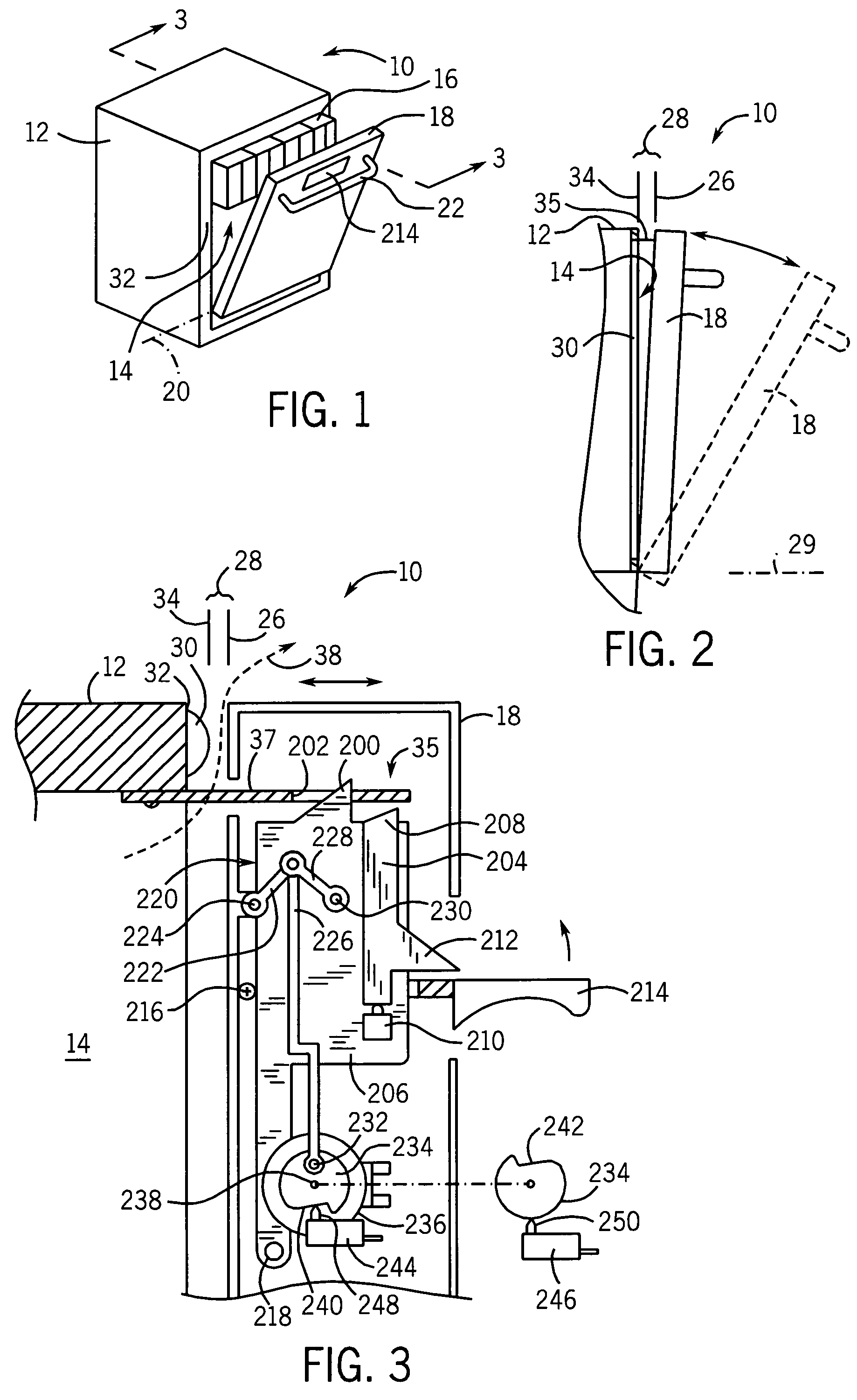
[0050]Referring now to FIG. 1, a dishwasher 10 includes a housing 12 partially enclosing a washing chamber 14, the latter holding racks 16 for suspending dishes and cutlery in the washing chamber 14. An open side of the washing chamber may be covered by a door 18 hinged to the housing 12 at a lower edge along a horizontal hinge axis 20. A front surface of the door 18 may include a towel bar 22, or in addition or alternatively, a door release lever 214.

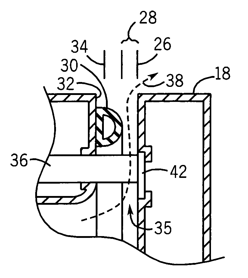
[0051]Referring to FIG. 2, the door 18 may swing between an open position 29 shown in phantom and a close position 26, in which the door 18 visually covers the washing chamber 14 but in fact is slightly displaced from a front lip 32 of the washing chamber 14 to provide a venting gap 28. The venting gap 28 may be, for example, a ¼-inch gap between the rear face of the door 18 and a gasket 30, the latter that provides a seal between the door 18 and front lip 32 of the washing chamber 14. The door 18 is held at this close position 26 prio...


PUM


Abstract

Automatic sealing of a dishwasher door is obtained through an electric actuator that moves the door from a close position adjacent to the opening of the washing chamber to a seal position in which the washing chamber is sealed typically against a gasket or the like. The actuator eliminates the need for the user to provide the force necessary to seal the gasket and/or can be used for improved venting of the washing chamber.

Description

CROSS-REFERENCE TO RELATED APPLICATIONS[0001]This application claims the benefit of U.S. Provisional Application 60 / 450,257 filed Feb. 25, 2003 which is hereby incorporated by reference.STATEMENT REGARDING FEDERALLY SPONSORED RESEARCH OR DEVELOPMENTBACKGROUND OF THE INVENTION[0002]The present invention relates to dishwashers for cleaning dishes and cutlery and more specifically to an automatic door for such dishwashers.[0003]A residential dishwasher may provide a washing chamber into which soiled dishes are placed and held by racks or the like. At the time of washing, the door to the chamber is closed and the dishes are sprayed with hot, soapy water. The door may include a gasket sealing the door against the chamber to prevent water leakage during the spraying process.[0004]Properly compressing the door gasket may require considerable force. This force may be applied by a vigorous pressing against the door by the user or by a lever-action latch offering sufficient mechanical advanta...

Claims


Application Information

Patent Timeline
IPC IPC(8): B08B3/00A47L15/42E05B17/00
CPCA47L15/4259E05B17/0029A47L2501/22
Inventor HAPKE, KENYON A.
Owner ILLINOIS TOOL WORKS INC
Why Eureka
Try Eureka