
Modular boiler control

a boiler control and module technology, applied in the field of module boiler control, can solve the problems of increasing requiring removal of control wiring, and requiring modification or replacement of existing external control, so as to facilitate the addition of boilers, reduce the cost of installation, and facilitate the effect of adding boilers

Active Publication Date: 2010-06-15
WESTCAST
View PDF16 Cites 9 Cited by
  • Summary
  • Abstract
  • Description
  • Claims
  • Application Information

AI Technical Summary

Benefits of technology

[0012]It is another object of the present invention to provide a modular boiler control that reduces costs associated with installing a multiple boiler system by eliminating the need for wiring between each individual boiler and a centralized external control.
[0018]It is another object of the present invention to provide a modular boiler control that directly detects a boiler having the least runtime among multiple boilers and adjusts the boiler firing sequence to evenly distribute runtime among the boilers.

Problems solved by technology

As will be appreciated, multiple boiler systems can be costly to purchase and install as they require significant wiring from the external control to each individual boiler.
The subtraction of a boiler from such systems requires removal of control wiring which can also be costly.
It is also possible that the existing external control may not have the capacity for an additional boiler and may require modification or replacement.
Additionally, if a boiler is not functioning properly or requires routine maintenance, it must be brought offline.
Such system-wide shutdowns can be undesirable particularly when the outside air temperature is low.
Further, if a boiler is not functioning properly manual adjustment of the external control may be necessary to adjust the firing of the other boilers to compensate for the faulted unit.
As will be appreciated, manual adjustment of an external control can be time consuming and can result in periods of insufficient heat until adjustment is complete.
Neither of these approaches, however, directly assesses which individual boiler has the least runtime.
If runtimes are not uniformly distributed, premature maintenance of the more frequently used boilers may be necessary.

Method used


Image

  • Modular boiler control
  • Modular boiler control
  • Modular boiler control

Examples


Embodiment Construction

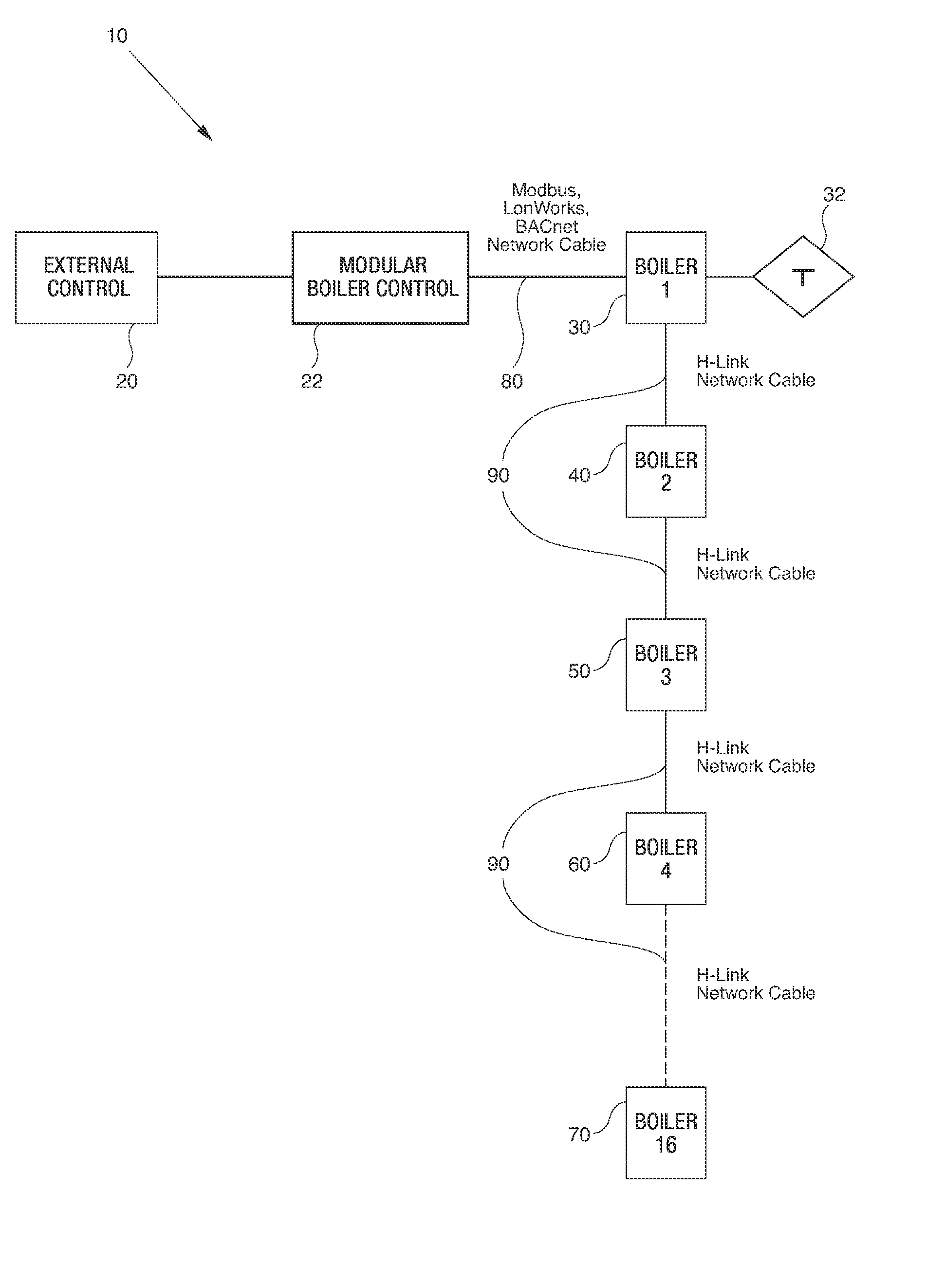
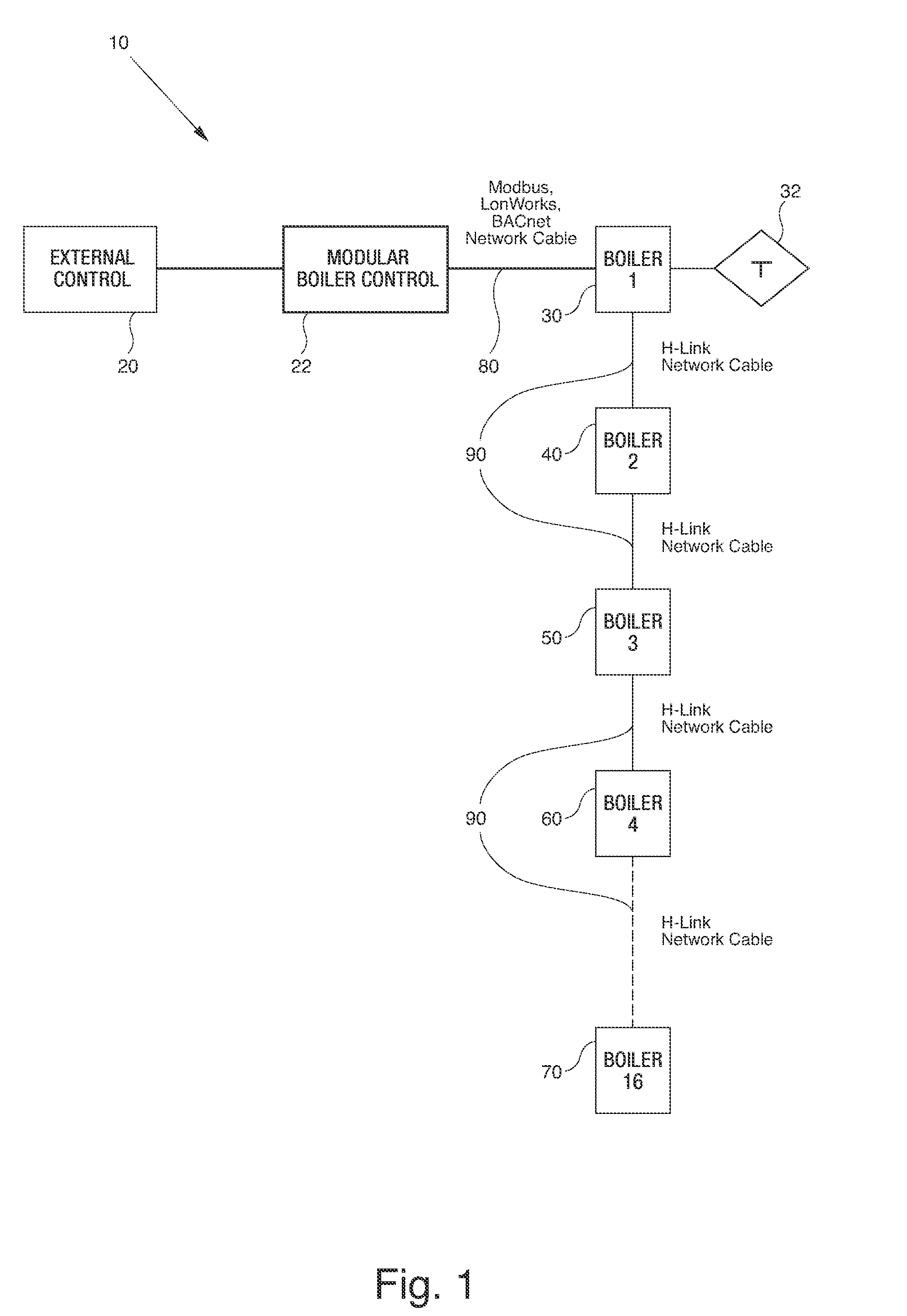
[0024]FIG. 1 is a simplified schematic illustration of a multiple boiler system 10 featuring a modular boiler control 22 according to one embodiment of the present invention. As shown in FIG. 1, the system 10 includes an external control 20 such as a building management system or a thermostat, a modular boiler control 22, and multiple individual boilers 30, 40. The external control 20 is connected to a first boiler 30 via a network cable 80. The first boiler 30 is also operatively connected to a temperature sensor 32. In the system shown in FIG. 1, the first boiler 30 is the “master boiler” as it is operatively connected to the system temperature sensor 32. The remaining secondary boilers, i.e., the “slave boilers”40 are serially connected to the master boiler 30, and to each other, by way of network cables 90. The master boiler is, by definition, the boiler connected to a system temperature sensor. As will be appreciated, the master boiler does not need to be the boiler directly co...


PUM


Abstract

A modular boiler system includes a boiler control, a first boiler in operative connection with the boiler control, and a temperature sensor in operative connection with the first boiler. The system also features at least one secondary boiler in operative connection with the master boiler. The boiler control is operatively connected to only the first boiler and it enables the first boiler to control a boiler parameter of the first boiler and the at least one secondary boiler.

Description

CROSS REFERENCE TO RELATED APPLICATIONS[0001]This application claims the benefit of U.S. Provisional Application Ser. No. 60 / 805,629, filed on Jun. 23, 2006, herein incorporated by reference in its entirety.FIELD OF THE INVENTION[0002]This invention relates generally to a modular boiler control, and more particularly to a modular boiler control in which a master boiler is networked with a least one slave boiler to control the heating loop of a structure.BACKGROUND OF THE INVENTION[0003]Known boiler systems include a boiler connected to an external control such as a thermostat or a building management system. The external control typically senses boiler temperature, controls boiler setpoint, performs outdoor reset functions and controls the boiler firing cycle.[0004]In multiple boiler systems, each boiler is connected to a single centralized external control from which all boiler operations are performed. The centralized control typically performs the above-listed functions for each ...

Claims


Application Information

Patent Timeline
Patent Type & Authority Patents(United States)
IPC IPC(8): F22B37/42B60H1/03B60H1/22F22D5/00F24D19/10G01M1/38G05B13/00G05B15/00G05B21/00G05D23/00
CPCF24D12/02F23N2037/02F23N2041/04Y02B30/14F24D2200/043Y02B30/108F23N2237/02F23N2241/04Y02B30/00
Inventor COHEN, KENNETH W.OSIENSKI, RICHARDHANNIGAN, BRIANRAWSON, MARKDEWEY, NATHANIELWILSON, JOHN
Owner WESTCAST
Learn More