Liquid material delivering method and device therefor

a liquid material and delivering method technology, applied in the direction of liquid transferring devices, liquid handling, instruments, etc., can solve the problems of affecting the functional effect specific to liquid materials, mixing of damaged parts or the like, serious damage to the plunger and the valve seat, etc., to reduce the amount of ejected liquid droplets, shorten the stroke (distance of movement) of the plunger, and reduce the volume produced by the movement of the plunger

Active Publication Date: 2010-06-15
MUSASHI ENG INC
View PDF14 Cites 2 Cited by
  • Summary
  • Abstract
  • Description
  • Claims
  • Application Information

AI Technical Summary

Benefits of technology

[0015]Further, to reduce the amount of the ejected liquid droplets, it is needed to shorten the stroke (distance of movement) of the plunger. On the other hand, the stroke (distance of movement) of the plunger must be increased from the viewpoint of obtaining the plunger speed sufficient to eject the liquid material in the form of flying droplets. In order to satisfy those contradictory demands at the same time, the metering section is designed to be relatively thin so that the distance of movement of the plunger is ensured which provides the plunger speed sufficient to eject the liquid material in the form of flying droplets. Also, with the thinning of the metering section, the volume produced by the movement of the plunger, i.e., the amount of the ejected liquid droplets, can be reduced even when the plunger is moved over a relatively large stroke.

Problems solved by technology

With such a known device, however, because the inertial force required for ejecting a liquid material in the form of flying droplets is obtained by abutting a moving solid plunger against a stationary solid valve seat and momentarily stopping the movement of the plunger, there arise problems that the plunger and the valve seat are seriously damaged by the abutting, and damaged plungers and valve seats must be frequently exchanged.
Another problem is that a damaged member or the like is mixed into the liquid material to melt therein.
In particular, when the delivered liquid material is a functional material, the mixing and melting of the damaged member may often disable the functional effect specific to the liquid material.

Method used


Image

  • Liquid material delivering method and device therefor
  • Liquid material delivering method and device therefor
  • Liquid material delivering method and device therefor

Examples


Embodiment Construction

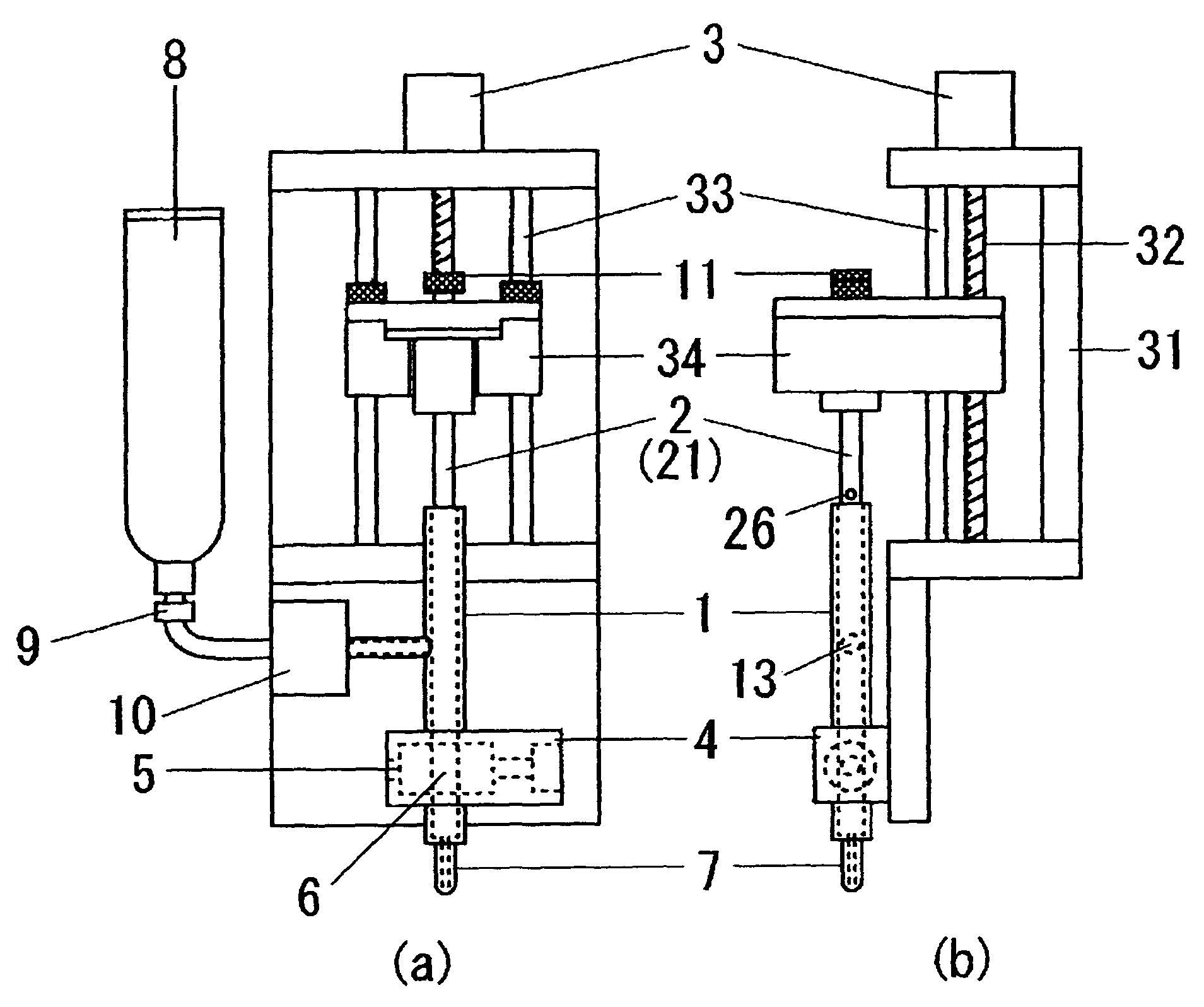
[0018]To explain the delivering method of the present invention in more detail, it comprises a first step of bringing a distal end surface of a liquid material delivering plunger into close contact with the liquid material, a second step of advancing the plunger at high speed, and a third step of abruptly stopping the plunger. The first step is performed at the time of initial setup or when trapping of air bubbles is confirmed. In most cases, the delivering operation is performed by repeating the second step and the third step. During the process of repeating the second step and the third step, because the distal end surface of the plunger is held in a state closely contacting the liquid material, the operation of “bringing the distal end surface of the plunger into close contact with the liquid material” is not performed unlike the first step.

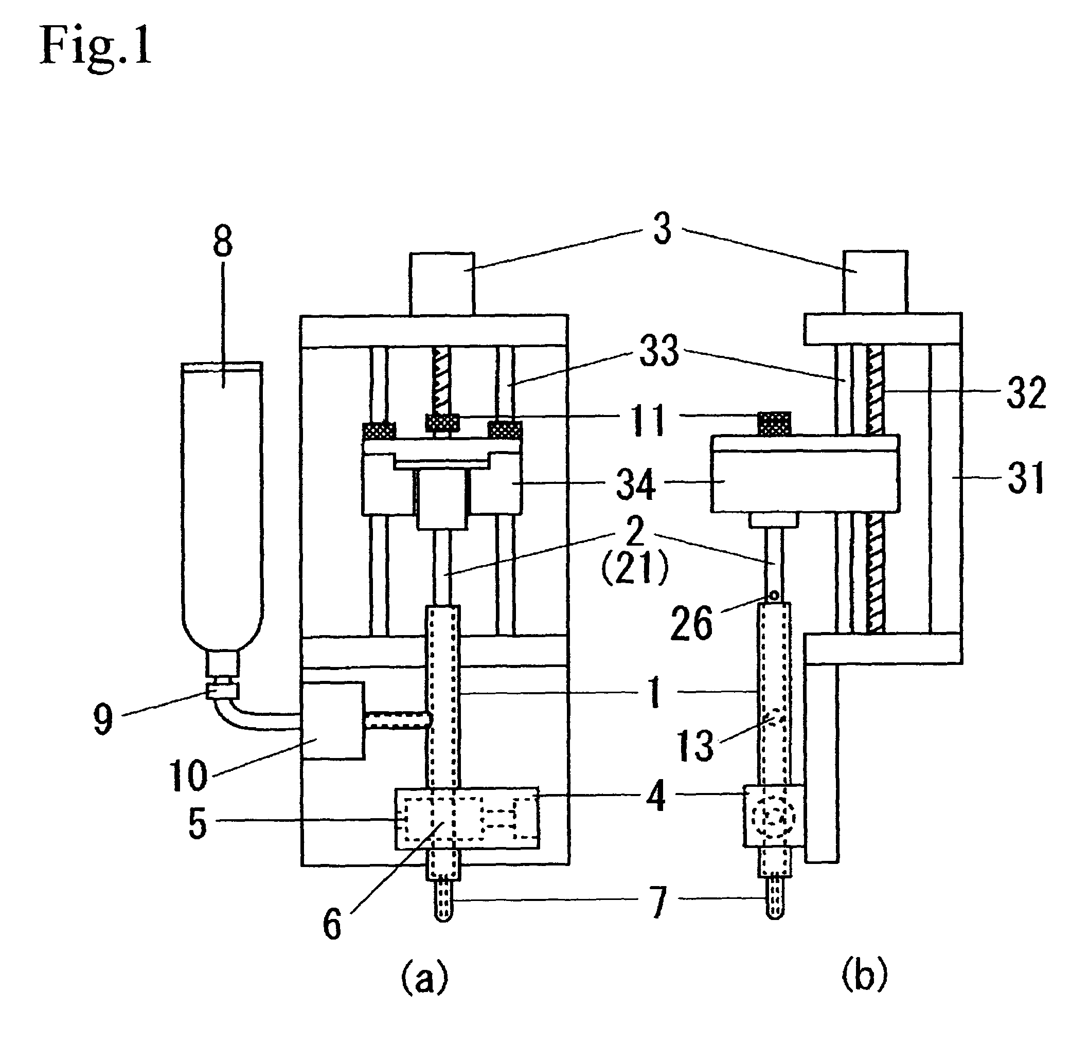
[0019]To explain the delivering device of the present invention in more detail, it comprises a tubular metering section, a plunger internally...


PUM


Abstract

A liquid delivering method and a liquid delivering device are provided, which solve the prior art problems including damages to a plunger and a valve seat. A liquid material delivering method includes the steps of advancing at high speed a liquid material delivering plunger with its distal end surface closely contacted with the liquid material, and subsequently abruptly stopping plunger driving means, thereby applying an inertial force to the liquid material to deliver the latter. A liquid delivering device includes a tubular metering section, a plunger internally contacting the metering section, a nozzle having a delivery port, a first valve for establishing communication between the metering section and the nozzle, a storage container for storing a liquid material, a liquid material feed valve (second valve) for establishing communication between the storage container and the metering section.

Description

TECHNICAL FIELD[0001]The present invention relates to the field in which a liquid material is delivered in a fixed amount through a nozzle delivery port by dripping or ejection in the form of flying droplets, and to the technique for delivering a liquid material at high accuracy in a clean state while preventing damages to components.BACKGROUND ART[0002]A known technique for ejecting a liquid material in the form of flying droplets employs a retracting and advancing plunger. The plunger is quickly accelerated to advance and then abruptly stopped by abutting it against a valve seat. Upon the abrupt stop, an inertial force is applied to the liquid material present in front of the plunger, thus causing the liquid material to eject in the form of flying droplets under the action of the inertial force.DISCLOSURE OF THE INVENTION[0003]With such a known device, however, because the inertial force required for ejecting a liquid material in the form of flying droplets is obtained by abutting...

Claims


Application Information

Patent Timeline
Patent Type & Authority Patents(United States)
IPC IPC(8): B65D88/54B05C5/02
CPCB05C5/0225B05C5/00B05D1/26
Inventor IKUSHIMA, KAZUMASA
Owner MUSASHI ENG INC
Why Eureka
Try Eureka