Advanced mechanical atomization for oil burners

a technology of mechanical atomizers and atomizers, which is applied in the field of advanced mechanical atomizers, can solve the problems of hurley atomizers not meeting the fluid droplet sizes provided, adding significantly to the cost of atomization, etc., and achieves the effect of reducing pressure and lowering pressur

Active Publication Date: 2010-06-15
CECO ENVIRONMENTAL IP INC
View PDF31 Cites 5 Cited by
  • Summary
  • Abstract
  • Description
  • Claims
  • Application Information

AI Technical Summary

Problems solved by technology

Achieving such high pressure adds significantly to the cost of atomization.
However, the Hurley atomizer does not achieve the fluid droplet sizes provided by the high pressure atomizers.

Method used


Image

  • Advanced mechanical atomization for oil burners
  • Advanced mechanical atomization for oil burners
  • Advanced mechanical atomization for oil burners

Examples


Embodiment Construction

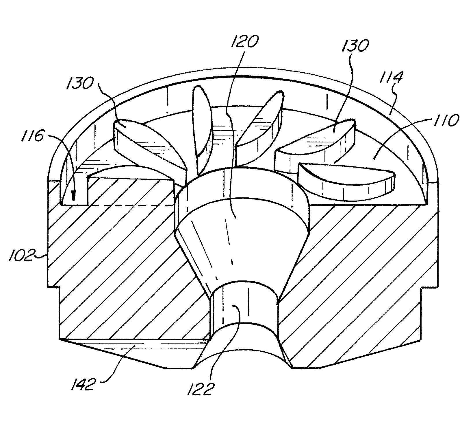
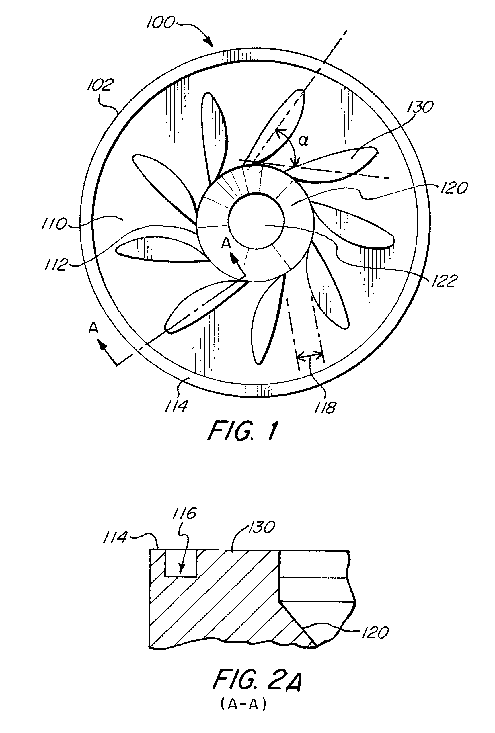
[0022]FIG. 1 shows a rear view of an atomizer spray plate 100 according to an exemplary embodiment of the present invention. The spray plate 100 includes a body 102. The body 102 may have any shape or size. For example, the shape and size may be selected to accommodate a particular application of the spray plate 100. In the present embodiment the body has a substantially cylindrical shape.

[0023]The spray plate 100 further includes an inlet portion having an inlet surface 110. In some embodiments, the depth of the inlet portion is shorter than inlets generally found in conventional mechanical atomizers. The inlet surface 110 includes a plurality of elongated protrusions or fluid deflectors 130 (e.g., islands). Better illustrated in FIGS. 2A and 2B, each protrusion 130 extends outward from the inlet surface 110. The protrusions 130 extend radially from an inner edge 112 and towards an outer edge 114 about the inlet surface 110. The protrusions 130 are preferably also situated at an an...


PUM


Abstract

An atomizer spray plate including a body having an inlet surface and an exit surface, a swirl chamber within the body and adjacent to the inlet surface, an atomizer hole extending through the body from the swirl chamber to the exit surface, and a plurality of elongated protrusions upon the inlet surface extending radially from the swirl chamber, wherein the plurality of elongated protrusions define a plurality of venturi inlets to the swirl chamber between adjacent protrusions.

Description

CROSS-REFERENCE TO RELATED APPLICATIONS[0001]This application claims priority benefits under 35 §U.S.C. 119(e) of the U.S. Provisional Application No. 60 / 791,605, filed on Apr. 12, 2006.FIELD OF THE INVENTION[0002]The invention relates to atomizers, and more specifically to an advanced mechanical atomizer for providing fine oil droplets for ignition in an oil burner.BACKGROUND OF THE INVENTION[0003]Atomizers are used in any number of applications to dispense or discharge fluids. For example, atomizers may be used for discharging fuel oil in an oil burner or boiler. Many different types of atomizers exist, one such type being a swirl atomizer. In swirl atomizers, liquid is generally directed into an atomizing nozzle or device having a swirl chamber. The liquid rotates in the swirl chamber and forms a thin conical sheet. The sheet is then directed via a hole or slot and breaks into ligaments and discrete particles or droplets upon exiting the nozzle. The droplets then mix with combust...

Claims


Application Information

Patent Timeline
Patent Type & Authority Patents(United States)
IPC IPC(8): B05B1/34
CPCB05B1/02B05B1/14F23D11/383F23D11/24B05B1/3436B05B1/3484
Inventor SCHINDLER, EDMUND S.LINDEMANN, SCOTTDALE, JOHN
Owner CECO ENVIRONMENTAL IP INC
Why Eureka
Try Eureka