Illuminating device and display device including the same

a technology of illumination device and display device, which is applied in the direction of fixed installation, lighting and heating apparatus, instruments, etc., can solve the problems of inability to adjust color balance, difficulty in exceeding 100% ntsc ratio with current color filter technique, and material having very high efficiency for emitted red light, etc., to achieve the effect of increasing efficiency and adjusting chromatic balan

Active Publication Date: 2009-01-13
HICKORY IP LLC
View PDF5 Cites 81 Cited by
  • Summary
  • Abstract
  • Description
  • Claims
  • Application Information

AI Technical Summary

Benefits of technology

[0008]An object of the present invention is to provide a light source for a display device, which includes a sufficient wavelength region of 600 nm or more, has intensity efficiency equal to or larger than that of a pseudo white LED, and can adjust chromatic balance even after manufacturing.

Problems solved by technology

In general, when the pseudo white LED is used as a light source, it is very difficult to exceed an NTSC ratio of 100% with a current color filter technique.
However, it is the fact that a material having very high efficiency is not found as a phosphor for emitting red light based on the blue excitation.
Further, a chromatic variation of the three-wavelength white LED is very large, so the color balance cannot be adjusted after the assembly of an LED package.
Thus, even when respective products (display devices) are composed of display panels, each of which has the same specification, it is impossible to avoid the occurrence of a chromatic difference between the respective products.

Method used


Image

  • Illuminating device and display device including the same
  • Illuminating device and display device including the same
  • Illuminating device and display device including the same

Examples


embodiment 1

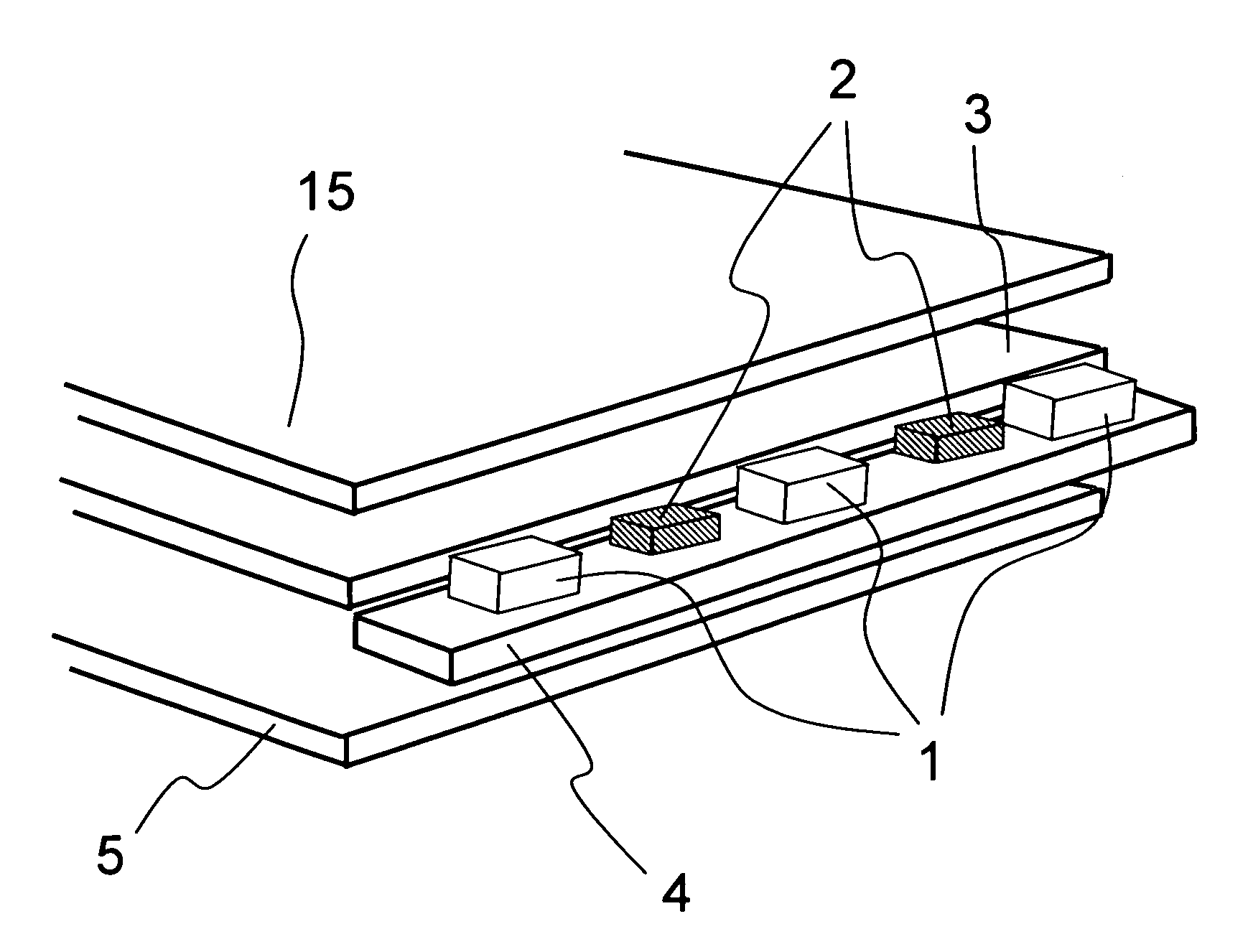
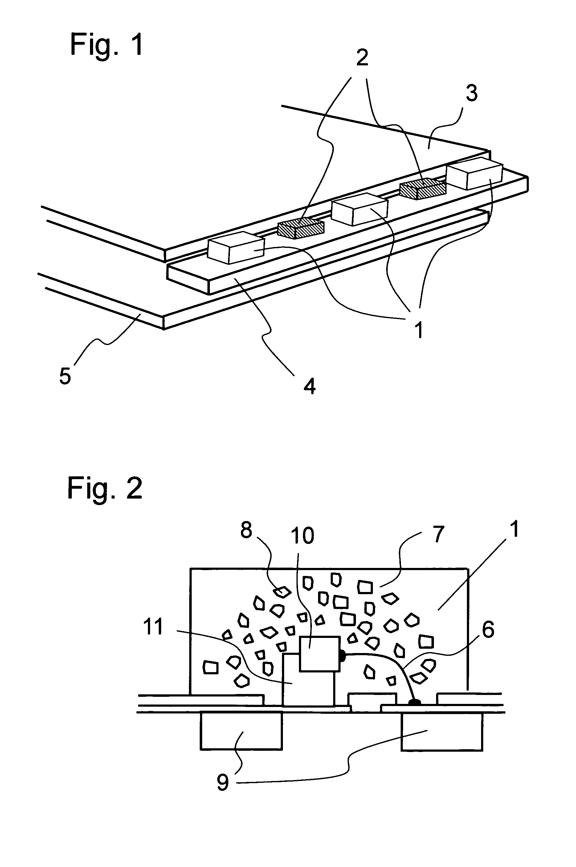
[0026]FIG. 1 schematically shows an outline of an illuminating device according to this embodiment. As shown in FIG. 1, blue-green LEDs (blue-green LED packages) 1 and red LEDs (red LED packages) 2 are mounted on a terminal portion of a circuit board 4 through solder. A material of each of the red LEDs 2 can be selected from GaP, GaAlAs, and AlGaInP to obtain an optimum wavelength and intensity. Each of the blue-green LEDs 1 emits light having a spectrum whose two peaks are caused in a wavelength of 450 nm to 480 nm and wavelength of 520 nm to 550 nm. The light emitted from each of the red LEDs has a peak in a wavelength of 600 nm or more. The light emitted from the blue-green LED 1 and the light emitted from the red LED 2 are mixed with each other by reflection and refraction which are repeated between a light guide member 3 and a reflecting plate 5, so that the resultant light becomes white light. Light emission intensities of the red LED 2 and the blue-green LED 1 can be controll...

embodiment 2

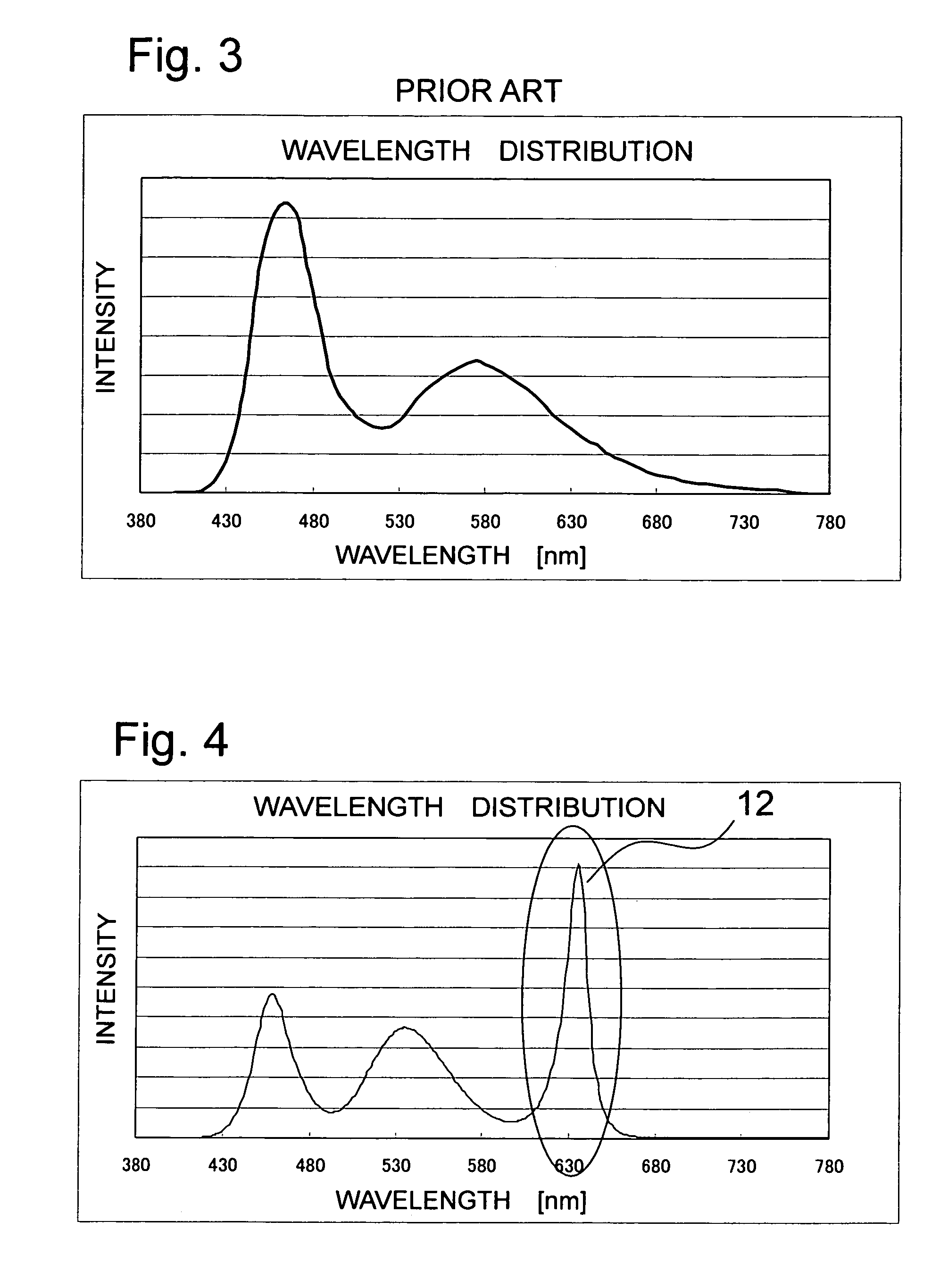
[0032]FIG. 6 is a schematic perspective view showing a structure of a liquid crystal display device according to the present invention. An LCD panel 15 having a color filter subjected to color tuning based on the light emission spectrum shown in FIG. 4 is disposed on a light emitting surface of the illuminating device, thereby constructing a liquid crystal display device whose intensity is very high and color reproducibility is high. An intensity adjusting circuit capable of controlling the light emission intensities of the red LED 2 and the blue-green LED 1 is further mounted. Therefore, by measuring intensity and a chromatic level after the completion of an LCD module and adjusting the light emission intensities of the red LED 2 and the blue-green LED 1, an LCD module having arbitrary white balance can be provided.

[0033]FIG. 7 is a schematic block diagram showing a circuit structure of the illuminating device used for a display device according to the present invention. A current ...


PUM

PropertyMeasurementUnit
wavelength regionaaaaaaaaaa
wavelengthaaaaaaaaaa

Abstract

Provided is a display device including: a light guide member for mixing light from a blue LED element coated with a translucent resin mixed with phosphor particles which converts blue light into green light with light from a red LED element to make white light exit from a light exit surface; and a non-self light emission display element provided on an irradiating surface side of the light guide member. Therefore, the display element is irradiated with white light whose sufficient wavelength region is 600 nm or more and whose intensity efficiency is high. When the display device further includes a circuit for separately controlling light emission intensities of the red LED element and a blue LED element, chromatic balance can be adjusted even after manufacturing and an intensity of the display device and color reproducibility thereof can be easily set in an optimum range even after assembly.

Description

BACKGROUND OF THE INVENTION[0001]1. Field of the Invention[0002]The present invention relates to an illuminating device for illuminating non-self light emission display elements and a display device used for electronic devices. In particular, the present invention relates to a liquid crystal display device used for a portable information device, a mobile telephone, and the like and an illuminating device used as a frontlight unit or a backlight unit to illuminate elements.[0003]2. Description of the Related Art[0004]In recent years, most of display devices used for a mobile telephone, a mobile computer, and the like are liquid crystal display devices capable of obtaining a high-definition color image with reduced power consumption. A liquid crystal element used for the liquid crystal display device is a non-self light emission type, so the liquid crystal element is illuminated by an illuminating device using a high-intensity white LED as a light source.[0005]In particular, used for ...

Claims


Application Information

Patent Timeline
Patent Type & Authority Patents(United States)
IPC IPC(8): F21V7/04F21S2/00F21S8/04F21V8/00F21Y101/02G02F1/13357
CPCH05B33/0821H05B33/0872G02F1/133615G09G3/3413H01L33/501H01L2224/45144H01L2224/48091H01L2224/48464H05B45/20H05B45/40H01L2924/00014H01L2924/00G02B6/00G02F1/1335
Inventor KURIHARA, MAKOTO
Owner HICKORY IP LLC
Why Eureka
Try Eureka