Light guide plate, surface light-emitting unit, and liquid crystal display device and method for manufacturing the same

a technology of liquid crystal display device and light guide plate, which is applied in the direction of lighting and heating apparatus, mechanical equipment, instruments, etc., can solve the problems of reducing the luminance ratio of a white display to a black display, reducing the contrast of the panel, and disadvantageously reducing the contrast, so as to achieve the effect of easy tight conta

Inactive Publication Date: 2005-02-03
ALPS ALPINE CO LTD
View PDF6 Cites 79 Cited by
  • Summary
  • Abstract
  • Description
  • Claims
  • Application Information

AI Technical Summary

Benefits of technology

[0041] Since the surface light-emitting unit is bonded to the liquid crystal display panel after a fluid ultraviolet curable resin is applied to at least one surface of the adhesive transparent resin films, the ultraviolet curable resin spreads over the entire surfaces of the adhesive transparent resin films so that bubbles are completely expelled from be

Problems solved by technology

Unfortunately, light is reflected from the air layer between the light guide plate and the liquid crystal display panel.
The reflected light disadvantageously decreases the contrast of the panel and therefore considerably decreases viewability.
Accordingly, the contrast, which is the luminance ratio of a white display to a black display, is disadvantageously decreased.
Additionally, tight contact between the light guide plate and the liquid crystal display panel is difficult due to

Method used


Image

  • Light guide plate, surface light-emitting unit, and liquid crystal display device and method for manufacturing the same
  • Light guide plate, surface light-emitting unit, and liquid crystal display device and method for manufacturing the same
  • Light guide plate, surface light-emitting unit, and liquid crystal display device and method for manufacturing the same

Examples


first embodiment

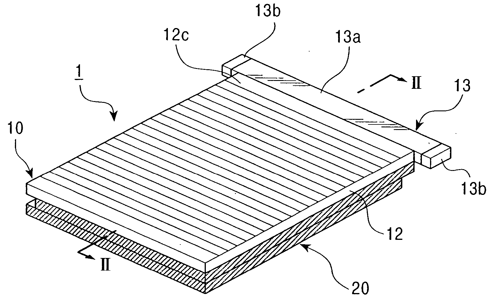
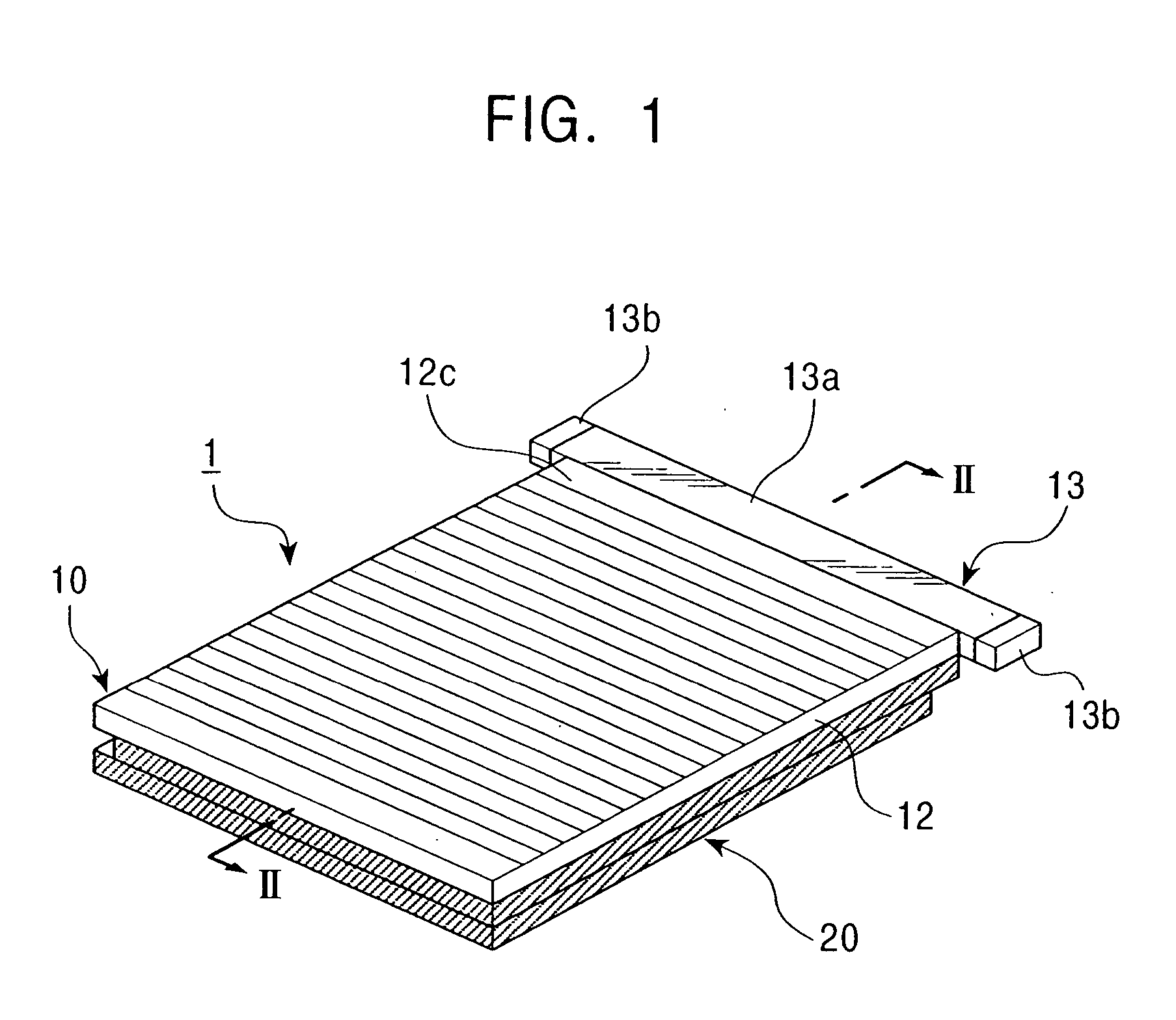
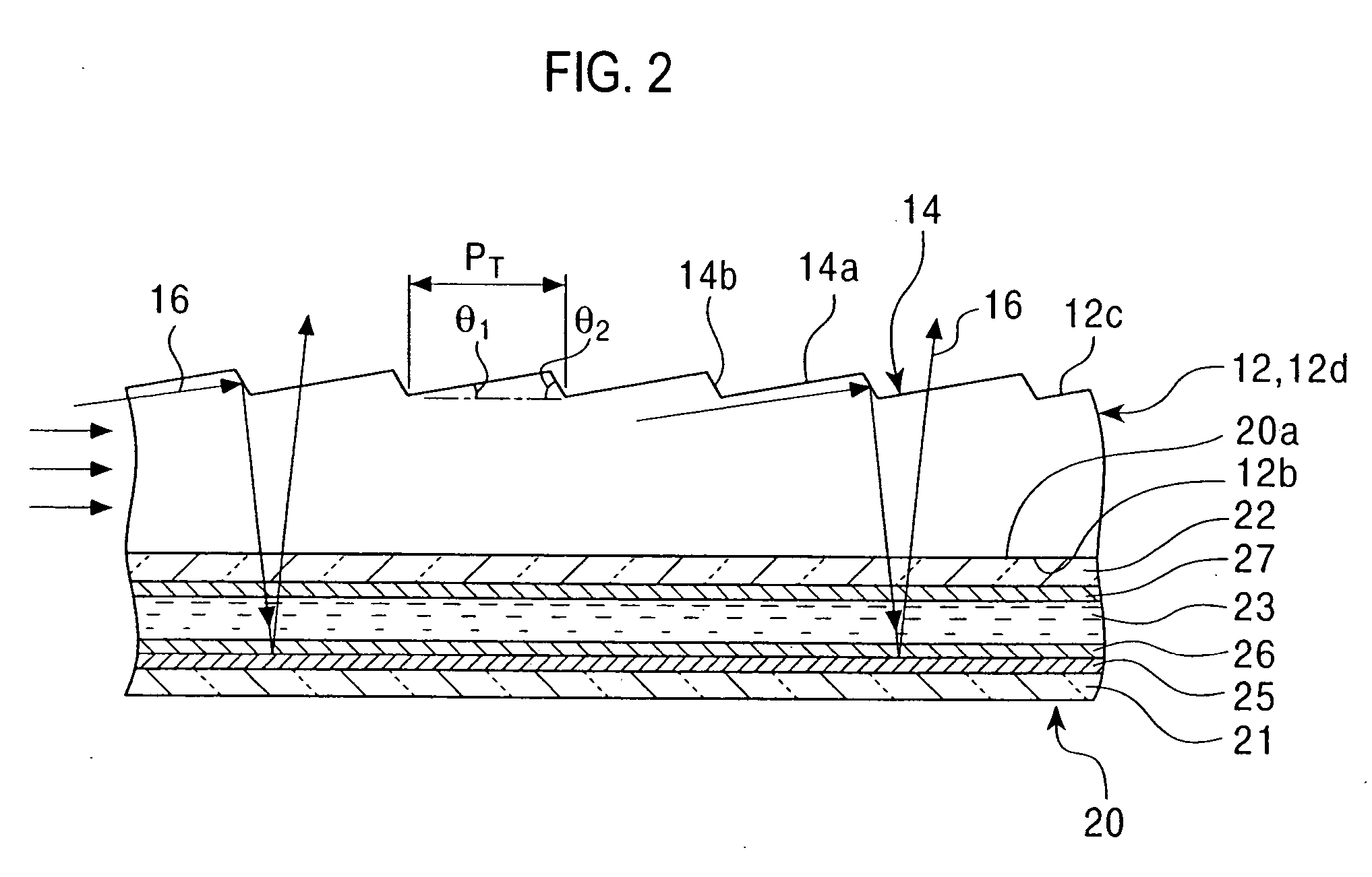
[0055] A first embodiment of the present invention will now be described with reference to the accompanying drawings. FIG. 1 is a perspective view of a liquid crystal display device according to the embodiment. FIG. 2 is a schematic sectional view taken along a line II-II in FIG. 1. FIG. 3 is an enlarged schematic sectional view of a relevant portion of the liquid crystal display device shown in FIG. 2. FIGS. 1 to 3 are drawings only for explaining the structure of the liquid crystal display device and, therefore, the scales for the dimensions and thicknesses of the elements are different from the actual ones.

[0056] As shown in FIGS. 1 and 2, a liquid crystal display device I according to the embodiment includes a liquid crystal display panel 20 and a front light (surface light-emitting unit) 10, which is disposed on the display surface 20a of the liquid crystal display panel 20 to illuminate the liquid crystal display panel 20. The front light 10 includes a transparent light guide...

second embodiment

[0070] A second embodiment of the present invention will now be described with reference to the accompanying drawings. FIG. 4 is a schematic sectional view of a liquid crystal display device according to this embodiment. FIG. 5 is an enlarged schematic sectional view of a relevant portion of the liquid crystal display device shown in FIG. 4. FIGS. 4 and 5 are drawings only for explaining the structure of the liquid crystal display device and, therefore, the scales for the dimensions and thicknesses of the elements are different from the actual ones. In FIGS. 4 and 5, the elements identical to those illustrated and described in relation to FIGS. 1 to 3 are designated by like reference numerals, and the descriptions are omitted or briefly stated.

[0071] As shown in FIGS. 4 and 5, a liquid crystal display device 51 according to the embodiment includes a liquid crystal display panel 20 and a front light (surface light-emitting unit) 60, which is disposed on the display surface 20a of th...

third embodiment

[0081] A third embodiment of the present invention will now be described with reference to the accompanying drawings. FIG. 6 is a schematic sectional view of a liquid crystal display device according to the embodiment. FIG. 7 is an enlarged schematic sectional view of a relevant portion of the liquid crystal display device shown in FIG. 6. FIGS. 6 and 7 are drawings only for explaining the structure of the liquid crystal display device and, therefore, the scales for the dimensions and thicknesses of the elements are different from the actual ones. In FIGS. 6 and 7, the elements identical to those illustrated and described in relation to FIGS. 1 to 3 are designated by like reference numerals, and the descriptions are omitted or briefly stated.

[0082] As shown in FIGS. 6 and 7, a liquid crystal display device 71 according to the embodiment includes a liquid crystal display panel 20, a front light (surface light-emitting unit) 10, which is disposed on the display surface 20a of the liq...


PUM


Abstract

A liquid crystal display device includes a liquid crystal display panel having a display surface, and a surface light-emitting unit on the display surface consisting of a light source and a light guide plate for introducing light emitted from the light source into the interior of the light guide plate and emitting the light from an exit surface thereof, wherein at least the exit surface is formed from a resilient material and the exit surface is in tight contact with the display surface of the liquid crystal display panel.

Description

BACKGROUND OF THE INVENTION [0001] 1. Field of the Invention [0002] The present invention relates to a light guide plate, a surface light-emitting unit, and a liquid crystal display device and a method for manufacturing the liquid crystal display device. [0003] 2. Description of the Related Art [0004] A front light is an efficient and superior surface-emitting light source that has been used for illumination of liquid crystal display panels. In general, a front light (surface light-emitting unit) includes a light source and a light guide plate. The light guide plate is usually disposed on the viewing side of a liquid crystal display panel, with an air layer therebetween, to illuminate the liquid crystal display panel. [0005] Unfortunately, light is reflected from the air layer between the light guide plate and the liquid crystal display panel. The reflected light disadvantageously decreases the contrast of the panel and therefore considerably decreases viewability. That is, the ligh...

Claims


Application Information

Patent Timeline
IPC IPC(8): F21V8/00G02F1/13357
CPCG02B6/0038G02F2001/133616G02B6/0055G02F1/133616
Inventor YAMAMOTO, KOICHINAGAKUBO, HIDEAKI
Owner ALPS ALPINE CO LTD
Why Eureka
Try Eureka