
Vibration absorbing mount for attaching an accessory to a portable power source

Inactive Publication Date: 2010-06-15
RELIANCE CONTROLS
View PDF13 Cites 3 Cited by
  • Summary
  • Abstract
  • Description
  • Claims
  • Application Information

AI Technical Summary

Benefits of technology

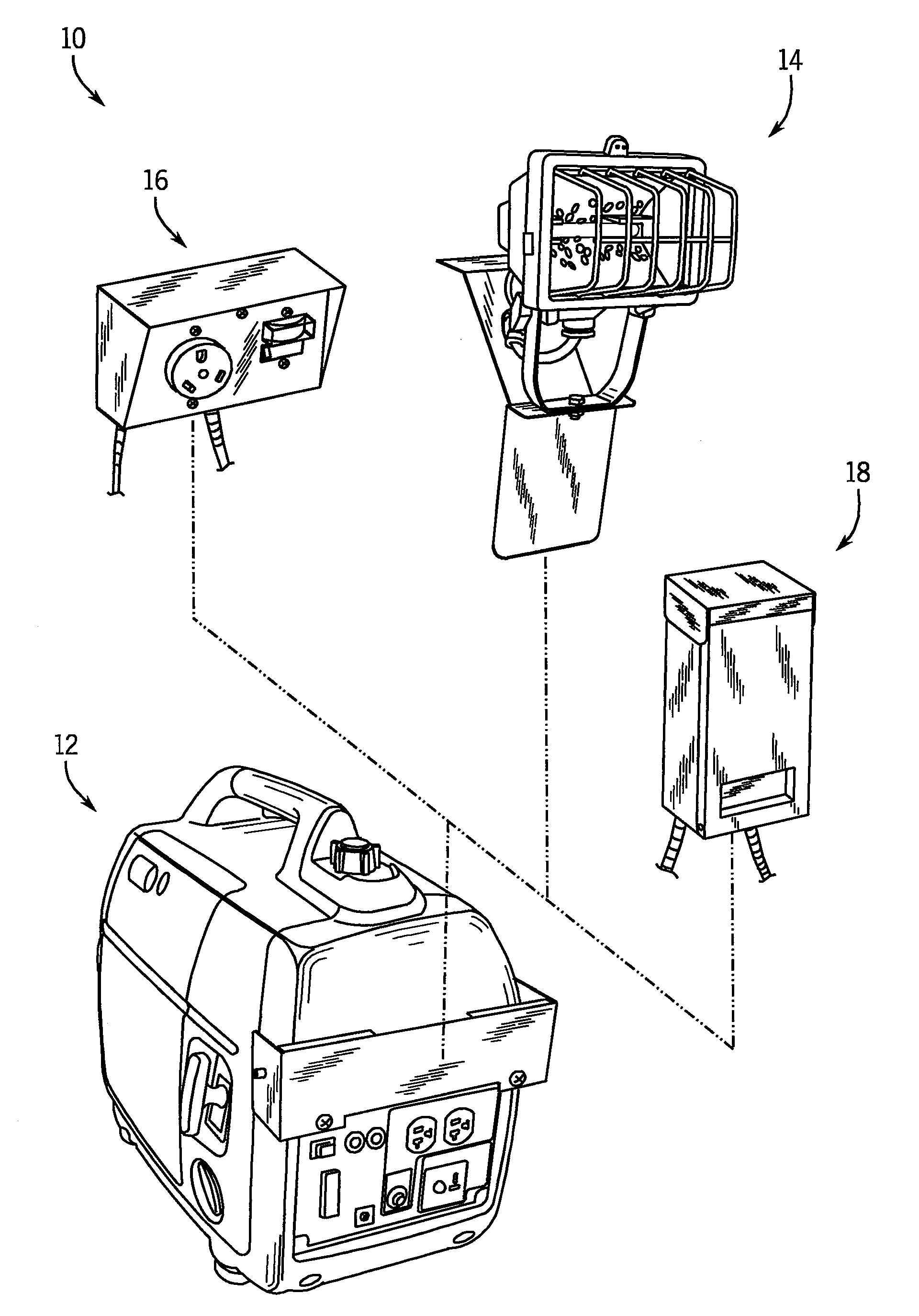
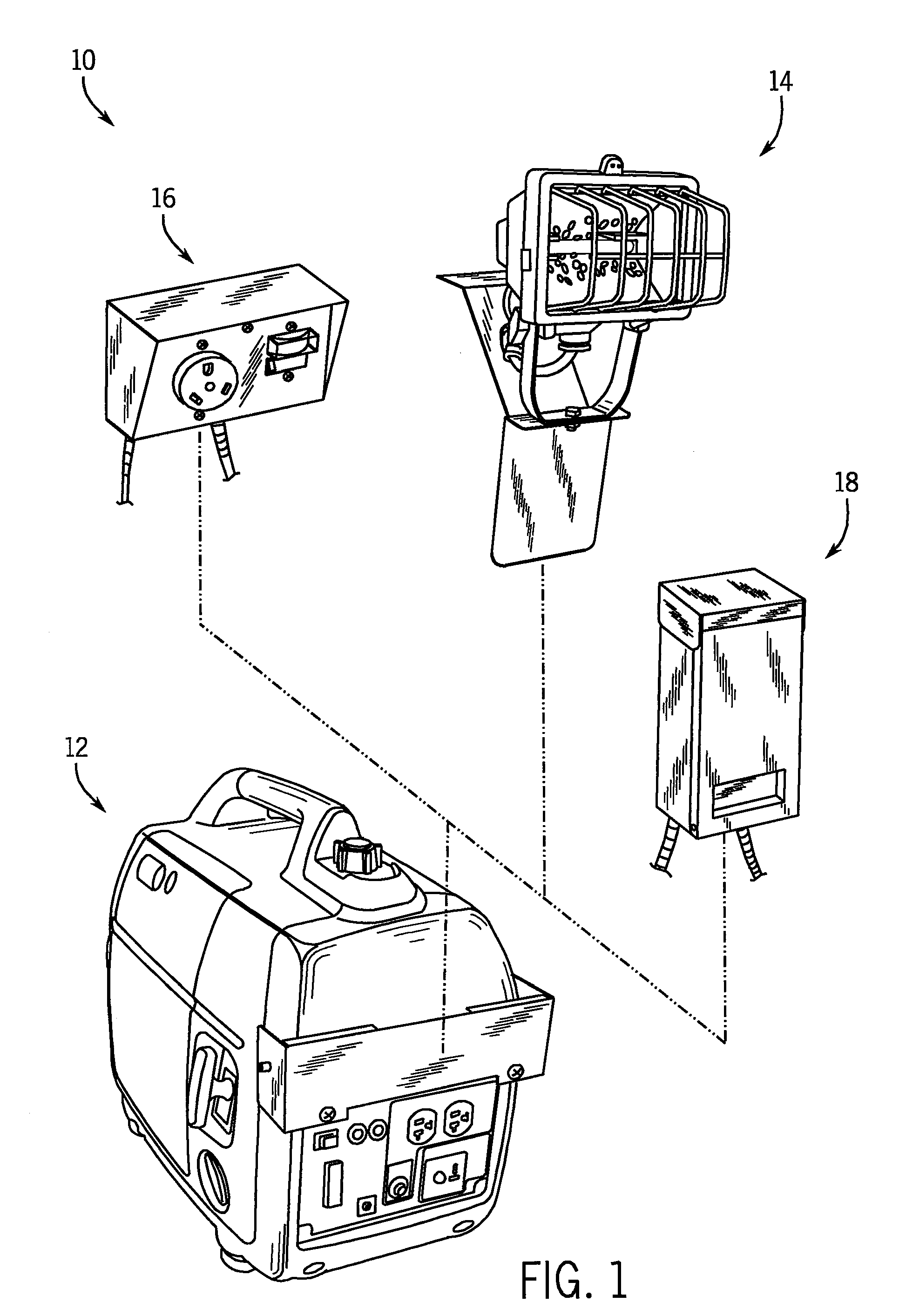
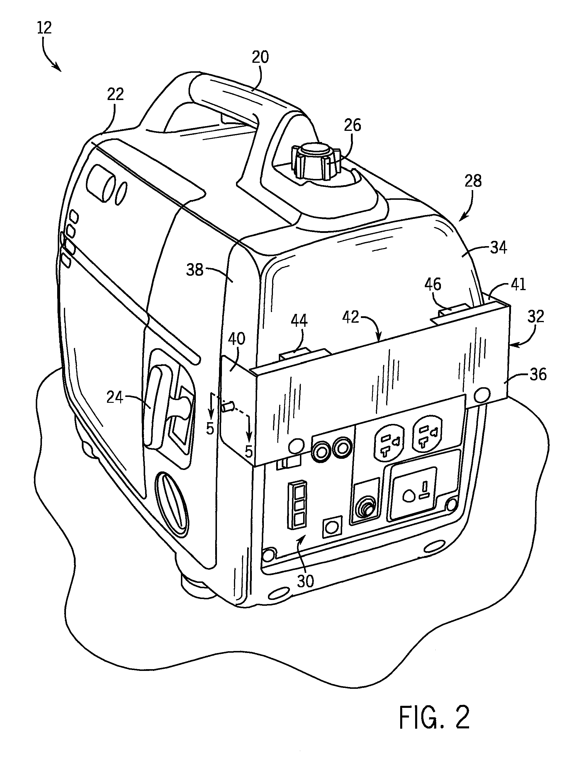
[0006]The vibration-reducing accessory mount of the present invention may be used in an embodiment in which the electrical accessory is permanently fixed to the mounting member, as well as an embodiment in which the electrical accessory is removably secured to the mounting member. In this regard, the vibration-reducing features may be incorporated into an accessory mounting arrangement that allows an accessory to be quickly and easily mounted to or removed from the generator. In one representative embodiment, the accessory mounting arrangement may be constructed such that tools are not required to mount the electrical accessory to the electric generator. The mounting member, including the vibration-absorbing cushion arrangement, is secured to the generator and the accessory, such as a parallel connection kit or a work light, is configured to be engaged with and removed from the mounting member in a tool-less manner. This construction provides an accessory mounting arrangement in which an accessory may be quickly and easily installed on or removed from a generator, and which also functions to reduce the transfer of vibrations from the running generator to the accessory.

Problems solved by technology

These power generators are typically large and heavy, and, as such, do not lend themselves to convenient portability.
Portable power generators, on the other hand, are much smaller and lighter.
In some situations, a single portable generator may be unable to provide the power demanded of a particular load.
Existing accessories such as work lights, parallel connection kits, transfer switches, etc. do not adequately account for the vibration caused by operation of the electric generator, which is transferred to the attached electrical accessory.
As a result, the light output by the work light may vibrate undesirably.

Method used


Image

  • Vibration absorbing mount for attaching an accessory to a portable power source
  • Vibration absorbing mount for attaching an accessory to a portable power source
  • Vibration absorbing mount for attaching an accessory to a portable power source

Examples


Embodiment Construction

[0032]The present invention will be described with respect to a portable, gas-powered generator to which electrical accessories may be mounted by a user, when desired, and then removed when not being used. While three exemplary accessories will be shown and described, it is recognized that these accessories are merely representative and that other accessories different from those shown may also be used. Moreover, it is recognized that the generator and accessories may be packaged and sold together as a bundle or kit, or that the generator and accessories may be commercially available separately. Additionally, while the invention is particularly suitable for hand-held, portable generators, it is understood that the particulars of the invention may also be applicable with non-portable generators. Similarly, the invention is not limited to gas-powered generators.

[0033]Also, while the present invention will be described with respect to vibration-reducing elements designed to reduce the ...


PUM


Abstract

A generator has an accessory mounting member adapted to mount an electrical accessory that provides isolation of the electrical accessory from the generator such that transfer of vibratory forces generated during operation of the generator is mitigated. The accessory mounting member allows an electrical accessory, such as a parallel connection kit, transfer switch, or work light, to be securely mounted to the generator, yet isolated from the vibrations that occur during operation of the generator.

Description

BACKGROUND OF THE INVENTION[0001]This invention relates generally to power generation devices and, more particularly, to an electric generator that incorporates vibration absorbing components so that vibrations generated during operation of the electric generator are not transferred to an electrical accessory mounted to the electric generator.[0002]Power generators may be characterized as either fixed or portable. Fixed power generators are commonly used as back-up or emergency power supplies for dwellings and buildings during main or utility power failure. These power generators are typically large and heavy, and, as such, do not lend themselves to convenient portability. Portable power generators, on the other hand, are much smaller and lighter. These power generators are typically used during light industrial applications or consumer recreational uses, such as camping. Portable power generators are also used to power selected circuits of a dwelling or other building during a util...

Claims


Application Information

Patent Timeline
IPC IPC(8): H02J7/00
CPCF16F15/08
Inventor FLEGEL, DAVID D.
Owner RELIANCE CONTROLS
Learn More